Effects
This section provides descriptions of all effects modules that are available in Kontakt, as well as explanations of their parameters.
This section provides descriptions of all effects modules that are available in Kontakt, as well as explanations of their parameters. Effects include dynamics tools, such as compressors, as well as audio processors that change the signal in a usually non-linear way, such as reverbs, flangers or distortion effects.
You can access these modules by clicking on the + icon in the lower right corner of each effects slot, which opens a drop-down menu of available effects.
Dynamics
Dynamic effects include the Compressor, Feedback Compressor, Limiter, Solid Bus Comp, Supercharger GT, Transient Master and Transparent Limiter.
Compressor
Compressors are dynamic tools which reduce the level of loud passages in a signal, thereby affecting the signal’s dynamic range. They are invaluable for a lot of common tasks — for instance, they can be used for reducing level peaks, thereby allowing the overall signal volume to be turned up without making it clip, or in other words, increasing the average volume of a signal. By careful adjustment of the attack and release times, they can also modify signal transients, allowing you to add punch to weak-sounding drums or taming exaggerated “clicking” in percussion sounds. However, there is a point of diminishing returns; too much compression can result in a rather strained and weak sound.
Compressor contains the following controls:

Mode: Choose between Classic, Enhanced, and Pro mode. Each of these settings provides a different flavor of compression; if you feel you can’t make a setting work with your sound, you should experiment with the other modes in this menu.
St.Link (Stereo link): When activated, this causes the compressor to always act on the left and right channel in unison; this preserves the stereo image. When deactivated, the Compressor becomes a dual mono processor, which means that both channels will be processed independently.
Thresh: Sets a level threshold above which the Compressor starts working. Only levels that rise above this threshold will be reduced by the compression; signals that stay below it will be left unprocessed.
Ratio: Controls the amount of compression, expressed as a ratio of input level change against output level change. A Ratio of 1:1 results in no compression. A Ratio of 2:1 means that a level increase of 2 dB at the input will raise the output level by only 1 dB. A 4:1 Ratio results in more aggressive compression, with a 4 dB level increase at the input causing a 1 dB increase at the output.
Attack: Adjusts the time the Compressor will take to reach the full Ratio value after an input signal exceeds the Threshold level. If you’re using compression mainly for transparent dynamic reduction, values between 5 and 10 ms are a good starting point. Longer attack times can be useful for emphasizing transients and adding “punch” to a signal.
Release: Adjusts the time the compressor will take to fall back to non-compression after the input signal falls below the threshold. Typical values range from 50 to 250 ms.
Output: Controls the module’s output level. This knob acts as a make-up gain control, which allows you to bring the output signal up to the same peak level as the input signal after compression. After you’ve found a compression setting, it’s good practice to adjust the input and output signals so they have comparable levels, and then compare them via the Bypass button. This way, you can make sure your adjustment really made the signal sound better (and not just louder).
Feedback Compressor
Compressors are dynamic tools that automatically reduce the level of loud passages in a signal, thereby affecting the signal's dynamic range. A feedback compressor is a type of compressor that compares the amplifier's output signal, rather than the input signal, to a threshold level. When the threshold level is reached, the compressor reduces the signal's gain level. The Feedback Compressor is modeled after a classic feedback compressor known for its bright and punchy sound.
Feedback Compressor contains the following controls:
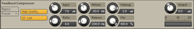
High Quality: Toggles oversampling within the effect, which can increase audio quality, but will also increase CPU load.
St. Link (Stereo link): When activated, this causes the compressor to always act on the left and right channel in unison; this preserves the stereo image. When deactivated, the Feedback Compressor becomes a dual mono processor, which means that both channels will be processed independently.
Input: Adjusts both the input level and the threshold simultaneously. Turning this knob clockwise will result in more compression.
Ratio: Determines the amount of compression. 1.0 means no compression at all, while 2.0 means that a 2 dB increase at the input will raise the output by only 1 dB.
Attack: Controls the scaling of the attack phase of the input signal's volume envelope. Increasing this parameter will add more punch and decreasing it will reduce sharp attacks.
Release: Determines how long it takes for the compression action to stop after the input signal falls below the threshold level. Typical values range from 50 to 250 ms.
Makeup: Controls the output gain of the compressed signal. Used to compensate for the gain reduction of the effect.
Mix: Controls the dry/wet mix of the compressor. This can be used to create a parallel compression style routing, which increases the quieter signals rather than reducing the louder ones. At a setting of 100% you will only hear the compressed signal; at a setting of 0% you will only hear the unprocessed input signal.
Output: Controls the module's output level.
Gain Reduction Meter: The meter to the bottom right shows the amount of gain reduction in dB.
Limiter
Limiters are actually a special form of compressors with a ratio of one to infinity, a threshold just below the maximum level, and a very short attack time. They act as a “safety net” to keep short signal peaks from overloading the system, which would result in audio clipping. While compressors have a range of artistic applications, limiters are usually used for technical reasons — they can tame signals with peaks which would otherwise overload the output, without requiring you to turn the signal’s overall volume down.
The Limiter contains the following controls:

In Gain: Sets the gain of the input signal. The Limiter is different from the Compressor in that it has a fixed threshold; to achieve a sensible peak reduction, use this control to adjust the input gain until you see the Attenuation meter responding only to occasional level peaks.
Release: Just like the Compressor’s control of the same name, this knob adjusts the time it takes the Limiter to return to an unprocessed signal after the input level falls below the threshold.
Attenuation: This LED-style meter shows the amount of gain reduction that the Limiter imposes on the signal. Limiting works best if this meter responds only to occasional level peaks; if it indicates permanent action, it’s a sure sign that your In Gain is set too high. This can considerably degrade the quality of your signal.
Output: Adjusts the module’s output level.
Solid Bus Comp
Compressors are dynamic tools which automatically reduce the level of loud passages in a signal, thereby affecting the signal’s dynamic range. The Solid Bus Comp is modeled after a classic analog bus compressor. It offers a more characteristic dynamic control than Kontakt’s standard compressor.
Solid Bus Comp contains the following controls:
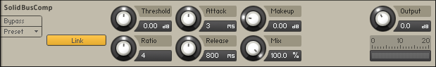
Link (Stereo link): When activated, this causes the compressor to always act on the left and right channel in unison; this preserves the stereo image. When deactivated, the Compressor becomes a dual mono processor, which means that both channels will be processed independently.
Threshold: Sets a level threshold above which the Compressor starts working. Only levels that rise above this threshold will be reduced by the compression; signals that stay below it will be left unprocessed.
Ratio: Controls the amount of compression, expressed as a ratio of “input level change” against “output level change”. A Ratio of 1:1 means that no compression will be happening. For example, a Setting of 4 represents the ration 4:1, which means for every 4 decibel increase of amplitude above the threshold, the output will increase by only 1 decibel.
Attack: Adjusts the time the Compressor will take to reach the full Ratio value after an input signal exceeds the Threshold level.
Release: Adjusts the time the compressor will take to fall back to non-compression after the input signal falls below the threshold.
Makeup: Controls the output gain of the compressed signal. Used to compensate for the gain reduction of the effect.
Mix: Controls the dry/wet mix of the compressor. This can be used to create a parallel compression style routing, which increases the quieter signals rather than reducing the louder ones. At a setting of 100% you will only hear the compressed signal, at a setting of 0% you will only hear the unprocessed input signal.
Output: Controls the module’s output level.
Supercharger GT
The Supercharger GT offers high-end tube compression emulation, inspired by boutique hardware. It is a particularly musical compressor, with different flavors of saturation and spectral shaping that allow you to apply subtle harmonic and spatial enhancement as well as heavy and aggressive tube drive.
Compressor tools affect both the dynamic range and color of a signal. They can be used for reducing level peaks, thereby allowing the overall signal volume to be turned up without clipping. They can also add coloration, character and warmth to a signal, which is especially inherent with tube-style compressors. Using Supercharger GT, you can stretch the decay phase of instruments, particularly drums, and add sustain to the tone of the electric guitars. Subtle compression applied to vocals helps to smoothen and balance their level within the mix. You can also try adding Supercharger GT to a Main Effects slot, and apply a slight amount of compression to your overall mix. Adding compression to the final signal path can add cohesion between various instruments, working like a glue that balances and binds sounds together.
Supercharger GT contains the following controls:
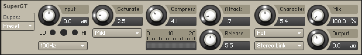 |
Input: Adjusts the input gain to the compressor in dB. The ideal setting of the Input is indicated by the Input Level Meter.
Input Level Meter: Displays the input level and indicates if the Input is set correctly. When the center LED lights up green, the Input level is at an ideal setting. If the Input level is too low, the left LED will light up red, and when it is too high, the right LED will light up red.
HP Detector: Selects one of three options (off, 100Hz, 300Hz) that determine if a high-pass filter is applied to the input signal. When set to 100Hz or 300Hz, the high-pass filter will cut the input signal below the selected frequency. Use this to prevent the compressor from reacting to low frequency signal peaks as induced by kick drums or bass instruments. This is especially useful when you using the Supercharger GT on the Main Effects chain.
Saturation: Applies saturation to the signal. Turn the control right to apply more saturation to the signal. The type of saturation is determined by the selected Saturation Mode.
Saturation Mode: Selects from three modes (Mild, Moderate, Hot) that determine the type of Saturation applied to the signal. Mild mode adds coloration to the signal whilst retaining a clean sound. Moderate mode adds more noticeable harmonics, and Hot mode applies maximum saturation and produces audible distortion.
Compress: Determines the amount of compression applied to the input signal. The higher the value, the more compression is applied to the input signal.
Gain Reduction Meter: Displays the amount of gain reduction in dB.
Attack: Determines how fast the compressor reacts to incoming signals. Increasing this parameter will add more punch and decreasing it will reduce sharp attacks.
Release: Adjusts the length of compressor's Release phase, which determines how long it takes for the compression to stop after the input signal falls below the Threshold level. Typical values range from 50 to 250 ms.
Character: Changes the sound characteristic of the compression effect by applying equalization to the signal. The type of equalization is determined by the selected Character Mode.
Character Mode: Selects from three modes (Fat, Warm, Bright) that determine the type of equalization applied. Fat mode emphasizes low and high frequencies. Warm mode rolls off high frequencies, while enhancing the lower frequencies. Bright mode enhances high frequencies and attenuates the lower frequencies of the signal.
Channel Link: Selects from three stereo modes (Stereo Link, Dual Mono, MS) that determine how the compressor is applied to the stereo channels. Stereo Link applies equal gain reduction to both the left and right channels. It is the most common mode as it eliminates the risk of shifting the stereo image. Dual Mono mode compresses each channel individually and can be used to widen the mix. In MS mode, the input signal will not be split into a left and right channel, but instead processed as mid and side signals. MS mode enhances the side signal to a certain extent, so signals processed using this mode may sound wider.
Mix: Controls the dry/wet mix of the compressor. This can be used to create a parallel compression style routing, which increases the quieter signals rather than reducing the louder ones. When the Mix control is set to 0%, only the uncompressed (dry) signal will be heard, and at 100%, only the compressed signal will be heard. Settings between the 0% and 100% are a mix of both signals.
Output: Sets the output level of the compressor in dB. You can use it as a make-up gain control that allows you to bring the output signal up to the same peak level as the input signal after compression. Once you have found a compression setting, it’s good practice to adjust the input and output signals so they have comparable levels, and then compare them via the Bypass button. This way, you can ensure that the compressed signal sounds better, not just louder.
Transient Master
The Transient Master is an easy to use compressor designed to control the attack and sustain of a sound. Instead of following the amplitude of the sound like a traditional compressor, it follows the general envelope and is thus not as susceptible to changes of input gain. It is best used on sounds with fast attacks, like percussion, pianos or guitars. The Transient Master can also be quite extreme in some cases, so use it with caution.
The Transient Master contains the following controls:

Smooth: Transient Master is designed mainly to work on drums or percussive material, so certain input signals (for example: an acoustic guitar) may not work ideally in the default mode, so try switching this button on if you are encountering problems.
Input: Controls the input gain to the effect.
Attack: Adjusts the scaling of the attack portion of the input signal’s volume envelope. Turning the knob right (0% to 100%) will add more punch, and turning the knob left (0% to -100%) will reduce sharp attacks.
Sustain: Controls the scaling of the sustain portion of the input signal’s volume envelope. Increasing this parameter will add more body to the sound and decreasing it will reduce the sound’s tail.
Output: Sets the output level of the effect in dB. For dynamic effects like compressors, this is very important.
Transparent Limiter
The Transparent Limiter has two key functions; to ensure that the signal level stays below 0 dB, thus avoiding digital clipping, and to increase the overall perceived volume of the signal. Preventing digital distortion is a safety measure that is fulfilled best by a limiter, as you are able to set a maximum output level via the ceiling control. The Transparent Limiter is perfect for this task, acting as a final means of protecting your signal from clipping without imposing too much coloration to your sound.
Reducing the Threshold will reduce the dynamic range of the signal, allowing you to boost the overall volume using the Output control. However, setting the Threshold too low can result in a squashed and dull sound. For best results, experiment with the Threshold and Release controls to see what works best for your signal. It is recommended to use the Transparent Limiter in the Main Effects section, as a final processor on your signal chain.
The Transparent Limiter contains the following controls:
 |
Threshold: Sets the threshold at which the limiter begins to affect the input signal. To prevent the signal from clipping, leave the Threshold at 0 dB. To make the signal louder, reduce the Threshold value by turning the control to the left. The Threshold can be set in the range from -40.0 dB to 0.0 dB.
Release: Adjusts the length of the release phase, which determines how long it takes for the limiter to stop after the input signal falls below the Threshold level. The Release can be set in the range from 1.0 ms to 500.0 ms.
Ceiling: Sets the maximum output level of the limiter in dB. A value of -0.3 dB is recommended to avoid any potential distortion on playback. The Ceiling can be set in the range from -40.0 dB to -0.3 dB.
Gain Reduction Meter: An LED style meter that displays the amount of gain reduction in dB. Limiting works best if this meter responds only to occasional level peaks; permanent gain reduction indicates that the Threshold is set too low.
Output: Adjusts the limiter's output level in dB.
Amplifiers
Amplifiers includes the ACBox, Bass Invader, Bass Pro, Cabinet, HotSolo, Jump, Twang and Van51 effects.
ACBox
The ACBox models the guitar amplifier sound that powered the British Invasion of pop music. There were many versions of this highly original amp made, each having a different character. We chose a model that stands out with a unique flavor and includes the famous Top Boost channel!
The Normal channel has a treble ToneCut control while the Brilliant channel offers Treble and Bass controls.
ACBox contains the following controls:
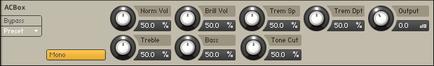
Mono: When this button is engaged, all channels of the input signal will be summed to a mono signal before being processed.When this button is not engaged, each channel is processed individually. Please note that this can increase the CPU load considerably.
NormVol: Sets the level for the Normal channel. The Treble and Bass controls have no effect in this channel.
BrillVol: Sets the level for the Brilliant channel.
TremSp: Sets the rate of the tremolo.
TremDpt: Controls the amount of tremolo applied. The effect is off when fully turned down.
Treble: Adjusts the high frequency response for the Brilliant channel.
Bass: Adjusts the low frequency response for the Brilliant channel.
ToneCut: Controls a low-pass filter. By turning the knob clockwise treble in the output of the Normal channel is reduced.
Output: Adjusts the module's output level.
Bass Invader
The Bass Invader models the sound of a versatile amplifier associated with the Rock and Indie sound of the late 1980s and 1990s. It includes extensive tone shaping controls that allow you to precisely tailor the sound. Although its character can be described as clean and sweet for most of its range, it also produces very interesting distortion sounds when the controls are cranked up.
This amp has been modeled using NI's newly developed ICM (Intelligent Circuit Modeling) technology that employs machine learning to reproduce the behavior of hardware devices from the ground up, giving a whole new level of depth and realism to amp emulations.
The Bass Invader contains the following controls:
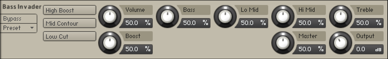 |
High Boost: Boosts high frequency content, adding edge and definition to the sound.
Mid Contour: Cuts low-mid frequency content, softening the sound.
Low Cut: Cuts low frequency content, removing rumble from the sound.
Volume: Adjusts the input level, or gain, of the amplifier. Turning Volume to the right adds saturation and distortion to the signal.
Boost: Adjusts the amount of extra gain added to the signal.
Bass: Adjusts the low frequency response.
Lo Mid: Adjusts the low-mid frequency response.
Hi Mid: Adjusts high-mid frequency response.
Treble: Adjusts the high frequency response.
Master: Adjusts the master volume of the amp.
Output: Adjusts the output level of the effect.
Bass Pro
The Bass Pro simulates a gritty and growling amplifier sound that makes the bass cut through the mix. It includes a graphic equalizer that allows you to precisely tailor your sound. This effect is available on both the Group and Instrument level.
The Bass Pro contains the following controls:
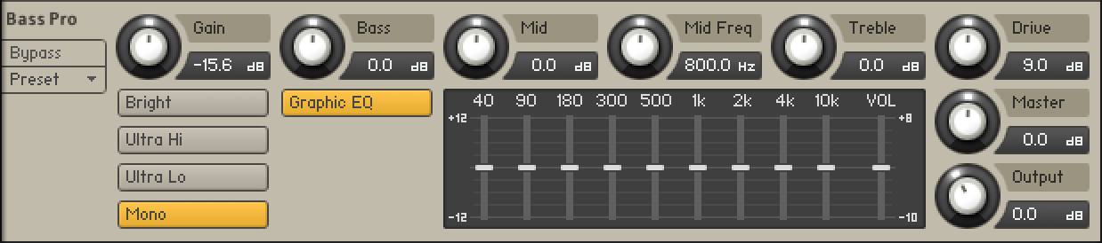 |
Bright: Boosts high-frequency content.
Ultra Hi: Boosts high-frequency content in a wide frequency range. The effect is more pronounced than the one achieved using Bright.
Ultra Lo: Boosts low-frequency content and cuts mid-frequency content.
Mono: When active, the module will work like a mono effect, causing stereo and multichannel signals to be summed to mono at its input. When inactive, each channel is processed separately. Note that disabling mono can increase CPU load considerably.
Graphic EQ: Activates the graphic equalizer in the lower panel of the amplifier.
Graphic EQ Gain: Boosts or cuts nine specific frequency bands: 40 Hz, 90 Hz, 180 Hz, 300 Hz, 500 Hz, 1 kHz, 2 kHz, 4 kHz, and 10 kHz. When a slider is centered, the respective frequency band remains unaffected. Moving a slider up boosts the respective frequency band by up to 12 dB. Moving a slider down cuts the respective frequency band by up to -12 dB.
Graphic EQ Volume: Adjusts the output level of the graphic equalizer. Moving the slider up increases the level by up to 8 dB. Moving the slider down decreases the level by up to -10 dB. You can use this control to compensate for strong boosts or cuts made with the graphic equalizer.
Gain: Adjusts the input level, or gain, of the amplifier. Turning Gain to the right adds saturation and distortion to the signal.
Bass: Adjusts the low-frequency response.
Mid: Adjusts mid-frequency content in a frequency band set using the Mid Freq control.
Mid Freq: Sets the frequency band adjusted using the Mid control from 200 Hz to 3200 Hz.
Treble: Adjusts the high-frequency response.
Drive: Adjusts gain specifically for mid-frequency content, thereby changing the character of the sound.
Master: Adjusts the master volume of the amp.
Output: Adjusts the output level of the effect.
Cabinet
Themodule simulates the sound of a guitar cabinet recorded through a microphone. By following a distortion effect (like the Skreamer) with this module in your insert chain, you can simulate a complete guitar amp.
Cabinet contains the following controls:

Cabinet Type: Allows you to choose the simulated cabinet model via the up and down buttons.
Size: Adjusts the size of the simulated cabinet. Larger cabinets tend to have a more pronounced bass response, while smaller cabinets can sound thin and tinny.
Air: Controls the level of early reflections in the room response, adding a sense of space to the sound.
TREB: Boosts or cuts the level of the higher frequencies.
BASS: Boosts or cuts the level of the lower frequencies.
Output: Adjusts the module’s output level.
EP Preamps
A collection of amplifiers, including distinct models for various preamps, EQs and tremolo effects.
EP Preamps contains the following controls:
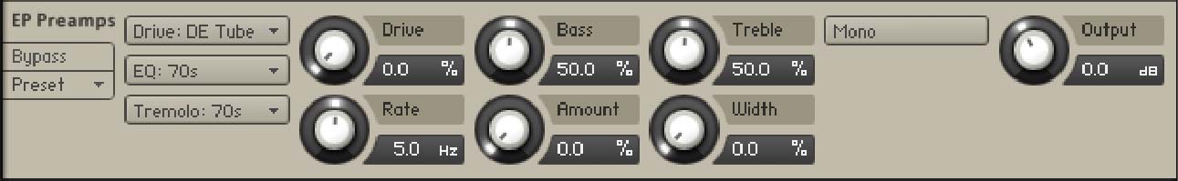
Drive Mode: Selects between four different preamp models, each with distinct characteristics.
EQ Mode: Selects between three different EQ models, each with distinct characteristics.
Tremolo Mode: Selects between four different tremolo models, each with distinct characteristics. Synth mode enables the subsequent Wave Mode menu.
Wave Mode: Selects one of five waveforms to be used for amplitude modulation (tremolo).
Drive: Adjusts the preamp input level or gain.
Bass: Adjusts the low frequency response of the EQ. When EQ Mode is set to Passive, this control is named Bass (P) and adjust the cutoff frequency of a high-pass filter instead.
Treble: Adjusts the high frequency response of the EQ. This control is not available when EQ Mode is set to Passive.
Rate: Adjusts the frequency or speed by which the tremolo effect modulates the amplitude of the signal.
Amount: Adjusts the amount of amplitude modulation (tremolo) applied to the signal.
Width: Adjusts the amount of stereo offset between left and right channel when applying amplutide modulation (tremolo) to the signal.
Mono: When active, the module will work like a mono effect, causing stereo and multichannel signals to be summed to mono at its input. When inactive, each channel is processed separately. Tremolo will always work in stereo.
Output: Adjusts the output level of the module in dB.
HotSolo
A model of a guitar amplifier that is considered to be a modern classic. HotSolo employs two separate preamplifier channels and heaps of gain for a distinctly contemporary rock sound.
HotSolo contains the following controls:
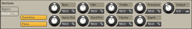
Overdrive: Switches between the Normal (when off) and Overdrive (when on) channels.
Mono: When this button is engaged, all channels of the input signal will be summed to a mono signal before being processed.When this button is not engaged, each channel is processed individually. Please note that this can increase the CPU load considerably.
Bass: Adjusts the low frequency response.
Mid: Adjusts the midrange frequency response.
Treble: Adjusts the high frequency response.
Presence: Boosts the frequency response in the upper midrange.
NormPre: Sets the preamp gain for the low gain channel.
OvrdPre: Sets the preamp gain for the high gain channel.
Master: Controls the overall output level.
Depth: Controls the low range frequency response in the power amp.
Output: Adjusts the module's output level.
Jump
The Jump effect simulates the classic tone of British guitar amplifiers. It is ideal for creating smooth, singing lead sounds. The Jump effect is available on both the Group and Instrument level.
Jump contains the following controls:
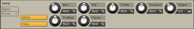
HiGain: Increases the preamp's gain potential. Switch to HiGain mode if you want to create distinctly distorted or saturated sounds.
Mono: When this button is engaged, all channels of the input signal will be summed to a mono signal before being processed. This happens regardless of the number of channels the input signal consists of, i.e. no matter whether it is a mono, stereo, or 5.1 signal.When this button is not engaged, each channel is processed individually. Please note that this can increase the CPU load considerably.
PreAmp: Sets the amount of gain added by the preamp. Turning it clockwise adds drive, distortion and edge to the sound.
Master: Adjusts the amp’s master volume.
Bass: Adjusts the low frequency response.
Mid: Adjusts the midrange frequency response.
Treble: Adjusts the high frequency response.
Presence: Boosts the frequency response in the upper midrange.
Output: Adjusts the module's output level.
Twang
The Twang effect simulates the rich tube sound of classic guitar amps from decades ago. It’s ideal for screaming leads and crunchy rhythm guitar sounds, as well as clean sounds with personality.
Twang contains the following controls:

Bright: A tonal option which increases the high frequency content of the signal.
Polyphonic: If this button is inactive, the Twang module will work as a mono effect, which causes stereo signals to be summed to mono at its input; when active, the effect operates on each input channel separately.
Volume: Controls the input level. In contrast to the Output knob, which merely adjusts the overall level of the module, this knob works like the gain control of a guitar amp and affects the amount of distortion.
Treble, Mid and Bass: These controls adjust the respective levels of the signal’s high, midrange, and low frequency components.
Output: Adjusts the module’s output level.
Van51
One of the benchmarks in high gain amplifiers. Van51 delivers a wide range of raw and edgy in your face guitar tones. The Van51 effect is available on both the Group and Instrument level.
V51 contains the following controls:
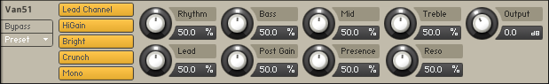
LeadChannel: Switches between Rhythm (when inactive) and Lead (when active) channels.
HiGain: Toggles between normal and high gain amplification.
Bright: When active, this adds high frequency boost in the Rhythm channel.
Crunch: Adds a large amount of distortion in the Rhythm channel.
Mono: When this button is engaged, all channels of the input signal will be summed to a mono signal before being processed.When this button is not engaged, each channel is processed individually. Please note that this can increase the CPU load considerably.
Rhythm: Controls the amount of preamp overdrive of the Rhythm channel.
Bass: Adjusts the low frequency response.
Middle: Adjusts the mid frequency response.
Treble: Adjusts the high frequency response.
Lead: Controls the amount of preamp overdrive of the Lead channel.
Post Gain: Controls the master volume of both channels and the poweramp saturation.
Presence: Boosts the frequency response in the upper midrange.
Reso: Controls the low range frequency response in the poweramp.
Output: Adjusts the module's output level.
Stomps
Stomp effects include the Cat, Cry Wah, Distortion, DStortion, Lo-Fi, Saturator, Skreamer and Tape Saturator.
Big Fuzz
Big Fuzz models the sound of a classic distortion pedal suitable for 1970s Rock guitars. Its sound character is dirty with a lot of grunge.
Big Fuzz contains the following controls:

Mono: When active, the module works like a mono effect, causing stereo signals to be summed to mono at the input. When inactive, each channel is processed separately.
Sustain: Adjusts the input level, or gain. Turning the control to the right increases the intensity of the distortion.
Tone: Adjusts the frequency respone. Turning this control to the left emphasizes high frequencies. Turning it to the right emphasizes low frequencies.
Bass: Adjusts the low frequency gain.
Bright: Adjusts the high frequency gain.
Output: Adjusts the module’s output level.
Cat
Cat simulates a guitar distortion pedal, ideal for blues and rock tones.
Cat contains the following controls:
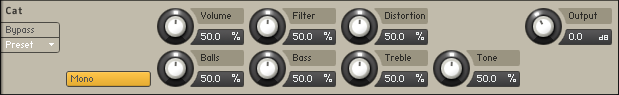
Mono: When this button is engaged, all channels of the input signal will be summed to a mono signal before being processed. This happens regardless of the number of channels the input signal consists of, i.e. no matter whether it is a mono, stereo, or 5.1 signal.When this button is not engaged, each channel is processed individually. Please note that this can increase the CPU load considerably.
Volume: The master volume control for the effect.
Filter: For a darker sound, turn clockwise to enhance the low frequency range; turn counter-clockwise for a brighter, sharper sound.
Distortion: Controls the amount of distortion applied.
Balls: Adds low-end punch. Turning it counter-clockwise creates a flatter, more biting sound.
Bass: Adjusts the low frequency response.
Treble: Adjusts the high frequency response.
Tone: Adjusts the frequency range influenced by the built-in pre-distortion midrange booster.
Output: Adjusts the module's output level.
Cry Wah
The Cry Wah has been imported from Guitar Rig 5 and is based on the most popular wah-wah of all time. This module creates a unique resonant peak that can be swept across the frequency spectrum using the Pedal control.
Cry Wah contains the following controls:

Pedal: The pedal control is used to control the wah-wah frequency. Decreasing the value will lower the frequency and increasing the value will raise the frequency.
Mono: If active, the module will work like a mono effect, which causes stereo signals to be summed to mono at its input. If inactive, it processes each channel separately.
Output: Use this control the make up gain from the clipping caused by the wah-wah effect.
Dirt
Dirt carefully provides more sophisticated and extreme sounds than possible with common distortion pedals, while staying true to the ease of use associated with these effects.
It consists of two circuit-modeled diode clipping stages (A, B) that can be configured in series or parallel using the Routing control. There are three modes of distortion (I, II, III) which can be used independently on each stage of the effect to set the type of clipping behavior. This allows you to explore different distortion characteristics and tonal qualities from subtle to more extreme.
The Drive control combined with the Amount control allow you to gradually increase the amount of saturation or distortion added to the signal. If the Amount control is increased beyond center position, the signal is folded back into itself, causing a more extreme distortion effect that adds strong harmonic overtones to the sound. By combining high settings for Drive and Amount on both stages, very rich and sustained sounds can be created by adding dirt and compression to the signal.
The distortion effect of each stage can be further adjusted using the Tilt control for filtering, and the Bias control for adding asymmetric behavior to the circuit, controlling the amount of even harmonics. Finally, when used in series the Mix control allows you to blend the dry and distorted signal to suit your mix, whereas in parallel mode the Blend control allows you to blend between the two stages A and B.
Dirt includes the following controls:
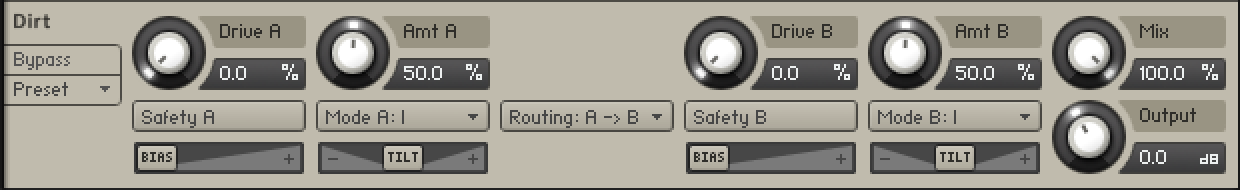
Safety A/B: Switches off the gain compensation that keeps consistent loudness levels. This can be used, for example, to drive a signal into the second stage at higher distortion levels.
Drive A/B: Adjusts the input level, or gain. Turning Drive to the right increases the intensity of the distortion.
Mode A/B: Selects one of three distortion modes to be used independently on stage A and stage B:
I is the most subtle mode and adds the least amount of coloring to the audio signal.
II is the default mode and is a well-balanced type of distortion with the brightest tone.
III is the most extreme mode which adds a crushed type of distortion with a dark tone.
Amount A/B: Adjusts the amount of distortion by introducing saturation in the first half of its range and wave folding in the second half. Instead of clipping the signal, wave folding folds the waveform of the signal back into itself.
Bias: Introduces asymmetry into the signal by adding asymmetric behavior to the circuit, which produces even harmonics. This prevents the distorted audio from sounding hollow.
Tilt: Applies filtering to the distorted signal. When turned to the right, low-frequency content is attenuated and high-frequency content is boosted. When turned to the left, low-frequency content is boosted and high-frequency content is attenuated.
Routing: Determines how the signal is routed between stage A and stage B of the effect.
A > B serial routing configuration: The signal is fed into stage A, then into stage B.
A < B serial routing configuration: The signal is fed into stage B, then into stage A.
A + B parallel routing configuration: The signal is split into both stage A and stage B before being mixed with the Blend control.
Mix: Blends between the dry signal and the wet signal by means of an equal-power crossfade. In A + B parallel routing configuration Mix is replaced with the Blend control, allowing you to blend between the output signals of stage A and stage B.
Output: Sets the output of the module in dB.
Distortion
This module causes distortion by clipping or rounding off high sample values. It thereby simulates the behavior of overloaded transistor or tube circuits, adding artificial harmonics to a sound.
Distortion contains the following controls:

Mode menu: Selects between either Tube or Transistor characteristics. Tube distortion creates a smooth saturation, which emphasizes even harmonics, while the Transistor setting generates odd harmonics that create a harsher-sounding clipping effect.
Drive: Adjusts the amount of distortion.
Damping: Turning this knob clockwise attenuates high frequencies in the output signal, thereby counteracting the brightness caused by the artificial harmonics.
Output: Adjusts the module’s output level. Since distortion boosts the gain considerably, it’s often necessary to attenuate the signal at the output stage.
DStortion
An emulation of a classic guitar distortion effect pedal.
DStortion contains the following controls:
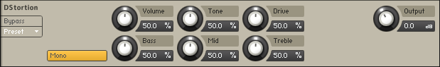
Mono: When this button is engaged, all channels of the input signal will be summed to a mono signal before being processed.When this button is not engaged, each channel is processed individually. Please note that this can increase the CPU load considerably.
Volume: The main volume control for this effect.
Tone: turning this control clockwise accents the midrange while dropping the bass. Counterclockwise takes off the highs and boosts the bass for a warmer sound.
Drive: adds dirt to the sound.
Bass: Adjusts the low frequency response.
Mid: Adjusts the midrange frequency response.
Treble: Adjusts the high frequency response.
Output: Adjusts the module's output level.
Fuzz
Fuzz models the sound of a 1960s fuzz pedal suitable for harmonically rich lead guitars that cut through the mix. Additionally, it can be used for buzzing vintage rhythm guitar.
Fuzz contains the following controls:

Mono: When active, the module works like a mono effect, causing stereo signals to be summed to mono at the input. When inactive, each channel is processed separately.
Amount: Adjusts the input level, or gain. Turning the control to the right increases the intensity of the distortion.
Bass: Adjusts the low frequency gain.
Bright: Adjusts the high frequency gain.
Output: Adjusts the module’s output level.
Saturator
This module is basically an amplifier with a non-linear characteristic. It allows you to recreate the effect of tape saturation, which causes an increase of high-level energy in your signal.
The Saturator contains the following controls:

Mode menu: Select the saturation type: Classic, Enhanced or Drums. Classic is the original Kontakt algorithm, Enhanced is a higher quality saturation mode and Drums is the saturation model used by Maschine.
Saturation: Adjusts the transfer curve. A negative setting results in a characteristic that will expand the signal — lower sample values will be attenuated, higher values will be amplified. Positive settings do the opposite and thusly simulate the compression-like saturation of an analogue circuit. At a value of 0.0, the signal will pass the module unprocessed.
Output: Adjusts the Saturator’s output level.
Skreamer
This module offers an alternate overdrive algorithm that sounds warmer and smoother than the Distortion effect.
Skreamer contains the following controls:

Tone: Controls the brightness of the sound. Turning this knob clockwise will result in a more pronounced top-end, which works great on bright, screaming leads and biting rhythms. Turning it counter-clockwise results in a mellower, darker sound.
Drive: Adjusts the amount of distortion.
Bass: Adjusts the low frequency gain.
Bright: Adjusts the high frequency gain.
Clean: Blends clean signal into the distorted tone. At 0.0 %, only the distorted signal is audible, while at 100.0 %, equal amounts of distorted and clean signal are mixed.
Output: Adjusts the module’s output level.
Lo-Fi
Bite
Bite is an anti-aliased sample rate and bit reduction effect that can be used to create distortion effects that sound like vintage studio equipment, or inherently lo-fi sound sources, like old video games. It simulates the audio being sampled and replayed using a low-quality sampler with limited sample rate and bit depth.
Bite is divided into two sections that control the resampling frequency (kHz) and the bit depth (Bits). As a special feature, the Crunch control adjusts the level going into the bit reduction algorithm, providing a smooth way to control the resolution without stepping effects.
The resampling algorithm also includes stereo clock jittering (Jitter), and the bit reduction algorithm provides stereo dither noise (Dither), allowing you to create a wide stereo image from any source. The additional controls for filtering and saturation allow you to fine-tune the behavior of the effect.
Bite contains the following controls:
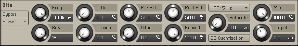 |
Freq: Adjusts the sampling frequency at which the input signal is resampled in a range of 0.1 kHz to 44.100 kHz.
Jitter: Adjusts the amount of clock jitter. This adds fluctuations to the sampling rate of the resampling algorithm, effectively making the signal noisier. The jitter is added to the left and right stereo channels independently, resulting in a wide stereo image for the noise component.
Pre Filt: Adjusts the cutoff frequency of a low-pass filter that is applied to the input signal. You can use it to remove frequencies that would produce aliasing noise in the resampling algorithm. At center position, the cutoff frequency is half of the sampling frequency. Its range is from 50 Hz to 22050 Hz.
Post Filt: Adjusts the cutoff frequency of a low-pass filter that is applied to the output signal. You can use it to remove aliasing noise. At center position, the cutoff frequency is half of the sampling frequency. Its range is from 50 Hz to 22050 Hz.
HP: Adjusts the cutoff frequency of a 1-pole high-pass filter that is applied to the output signal. It aims remove low-frequency and DC components from the signal. It provides three cutoffs 5 Hz, 100 Hz and 200 Hz.
Saturate: Drives the quantized signal into a saturator and compensates for the loudness increase caused by the saturation.
Bits: Adjusts the amounts of quantization values by setting the bit depth between 2 and 16 bits. Each sample is quantized to the set values. A lesser amount of values results in a more distorted sound.
Crunch: Provides continuous control over the bit reduction effect, reducing the amount of used quantization values by lowering the signal level before the bit reduction algorithm. This allows you to smoothly control the resolution without stepping effects.
Dither: Adjusts the amount of noise that is added to the resampled signal to reduce distortion caused by quantization errors. In this effect, the noise amount can be increased for creative purposes. Independent noise sources are used for left and right stereo channels, resulting in a wide stereo image for the noise component.
Expand: Changes the distribution of the quantization values in the amplitude range. When set fully to the left, low-level signals are quantized at a higher resolution. When set fully to the right, the resolution available for quantizing low-level signals is reduced, effectively turning them into pulse waves.
DC: Toggles between two different modes for the quantization of the input signal according to the bit depth (Bits). When activated, the zero level is removed from the available bit values, effectively sustaining the sound with a buzzing square wave. When deactivated, the output signal fades to silence immediately.
Mix: Blends between the dry signal and the wet signal by means of an equal-power crossfade.
Output: Adjusts the output level of the module in dB.
Lo-Fi
This module adds various digital artifacts, like quantization noise or aliasing, to a clean signal. It’s great for roughing up sounds that would otherwise be too plain and featureless.
LoFi contains the following controls:

Bits: Re-quantizes the signal to an adjustable bit depth. Fractional bit levels (such as 12.4 bits) are possible and can add considerable “grit”. Audio CDs have a quantization depth of 16 bits, old samplers frequently used 8 or 12 bits, and 4 bits evoke memories of countless irritating children’s toys.
S.Rate (Sample Rate): Re-samples the signal to an adjustable sample rate. The re-sampling is done without any kind of (usually mandatory) low-pass filtering, which causes all kinds of wonderful aliasing artifacts. The sample rate goes all the way down to 50 Hz, which will not leave much of the original signal.
Noise: Adds hiss to the audio signal.
N.Color: Adjusts the frequency characteristic of the noise and acts as a low-pass filter.
Output: Adjusts the module’s output level.
Tape
Tape Saturator
The Tape Saturator emulates the soft compression and distortion of recording to tape. It can be used lightly to add warmth and coloring to the sound, or heavily to add aggressive distortion.
TheTape Saturator contains the following controls:

High Quality: Toggles oversampling within the effect, which can increase audio quality, but will also increase CPU load.
Gain: Controls the input gain of the effect. This will increase the amount of tape distortion and compression.
Warmth: Controls the low frequency boost/cut of the effect.
HF Rolloff: Controls the high frequency rolloff starting frequency. Frequencies above this point will be attenuated.
Output: Controls the output gain of the effect.
Wow/Flutter
Wow/Flutter emulates the sound of analog tape machines, characterized by wow and flutter, saturation, noise, and a limited high-frequency response. You can use it to apply classic lo-fi effects, particularly when playing sustained notes, pads and melodies.
Dedicated controls for Wow, Flutter, as well as the Speed and Age of the tape enable you to adjust the effect in great detail. The Scrape control expands the sound palette by degrading the sound and adding a crunchy quality.
Wow/Flutter includes the following controls:
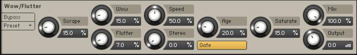
Scrape: Adjusts the amount of high-frequency scraping, which occurs when the tape vibrates as it passes over the playback head.
Wow: Adjusts the amount of wow, a slow fluctuation in pitch caused by sticky tape and worn-out tape transport.
Flutter: Adjusts the amount of flutter, a fast fluctuation in pitch caused by a bent capstans and faulty motor parts.
Speed: Adjusts the rate of the wow and flutter modulation.
Stereo: Adjusts the stereo width of Wow and Flutter by adding a phase offset to the modulation applied to the the left and right stereo channels.
Age: Enhances the characteristics of an aging tape by reducing high-frequency content and introducing tape hiss.
Gate: Toggles the noise gate on or off. When enabled it will remove low level tape hiss noise one second after receiving the last input signal.
Saturate: Adjusts the amount of tape saturation from a clean sound to overdrive.
Mix: Blends between the input signal and the effect signal by means of an equal-power crossfade.
Output: Sets the output of the module in dB.
Modulation
Modulation effects include the Choral, Flair, Phasis, Rotator, Legacy Chorus, Legacy Flanger and Legacy Phaser.
Choral
Choruses are used to enrich sounds by adding spatial movement and giving them an ensemble-like quality. They are based on short delays, with built-in modulation of the delay time. The delays produce copies of the original sound that vary in timing and, as a side-effect of the delay time modulation, pitch. This way a chorus adds space and body to the sound as if it was played from multiple sources at the same time. The results range from subtle shifts in timbre to extremely lively textures with a wide stereo image.
As one of the most commonly used guitar and studio effects, various implementations of the chorus have found their way into studio rack processors, guitar pedals, and synthesizers. Choral is inspired by synthesizers and studio rack processors from the seventies and early eighties. On these devices, the chorus parameters are hidden. Choral gives you enhanced control with parameters that allow you to customize the effect with minimal effort.
Choral features four distinct chorus modes, ranging from the subtle sound of classic studio rack processors to the large ensemble sound of early string synthesizers. The effect is produced by up to three pairs of delays, called Voices. All chorus voices preserve the input signal’s stereo image, but can also be panned to further widen the sound (Width parameter). The internal modulation system affects each voice differently, thus preventing obvious modulation repeats. Further expanding on the original concept of a chorus, the Scatter mode allows you create reverb-like sounds, avoiding the metallic quality that many choruses exhibit with high Feedback settings.
Choral contains the following controls:
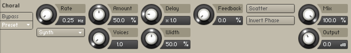 |
Rate: Adjusts the speed of modulation, from slow pitch changes to fast vibratos. This becomes more pronounced as Amount is increased.
Mode: Switches between four chorus modes (Synth, Ensemble, Dimension, Universal), that determine the sound characteristic and modulation behavior.
Synth: This mode is inspired by the choruses of polyphonic synthesizers from the late seventies and early eighties. Its sound characteristic is dark and vintage. The modulation behavior is tuned for rich and dispersed sounds.
Ensemble: This mode is inspired by the choruses of string synthesizers from the seventies. Its sound characteristic is warm and lush. The modulation behavior is tuned for animated and lively sounds.
Dimension: This mode is inspired by the choruses of studio rack processors from the early eighties. Its sound characteristic is bright and transparent. The modulation behavior is tuned for wide and consistent sounds.
Universal: This mode is a more generic chorus implementation. Its sound characteristic is clean and modern. The modulation behavior is tuned for a range of sounds from consistent to lively, depending on the number of Voices.
Amount: Adjusts the amount of modulation applied to the Delay, altering the delay times of the chorus voices. Due to the configuration of the delays, this also changes the pitch of the chorus voices, creating the typical chorusing effect.
Voices: Fades from one to three chorus voices. Increasing the number of chorus voices adds a dense and ensemble-like quality to the sound. The modulation affects the second and third chorus voice differently from the first, resulting in a wider and livelier sound.
Delay: Adjusts the delay times of the chorus voices, allowing you to change the spatial depth of the sound. This parameter strongly interacts with Feedback.
Width: Pans the chorus voices in opposite directions, widening the stereo image. When Width is set to 0, the stereo image of the input is preserved.
Feedback: Adjusts the level of the feedback signals from the outputs of the chorus voices to their inputs, creating a more sustained and spacious sound.
Scatter: Enables a special feedback routing for the chorus voices that introduces reverb-like behavior.
Mix: Blends between the input signal and the effect signal by means of an equal-power crossfade.
Invert: Changes the sound characteristic of the chorusing effect by inverting the effect signal.
Mix: Blends between the input signal and the effect signal. When the knob is turned fully left, only the dry input signal is heard.
Output: Adjusts the module’s output level.
Flair
Flangers are used to enrich sounds by adding distinct harmonic effects that can completely transform a sound. They are based on comb filters, with built-in modulation of the comb filter frequency. A comb filter consists of an extremely short delay with feedback that produces harmonically related peaks and notches in the frequency spectrum. This way a flanger adds dramatic filtering effects and resonances to the sound. The results range from metallic textures to the warped sound of a starting jet engine.
As one of the most commonly used guitar and studio effects, various implementations of the flanger have found their way into studio rack processors and guitar pedals. Flair is a new take on the concept with additional features that have been carefully chosen to allow for more sophisticated and extreme sounds than possible with common flangers, while staying true to the ease of use and clarity associated with these devices.
Flair features three flanger modes that offer different approaches to a range of effects from flanging to harmonization. The effect is produced by up to four comb filters, called Voices. Further expanding on the original concept of a flanger, the flanger voices have a harmonic relationship based on a wide selection of preset chords (Chord parameter). In both Standard and Thru Zero mode, the flanger voices are added to form a chord, while in Scan mode, one flanger voice is blended into the next, generating a sequence similar to an arpeggiator on a keyboard. Especially with high feedback settings, this can lead to unusual results that are more akin to the sounds of a tuned resonator than a flanger.
Flair contains the following controls:
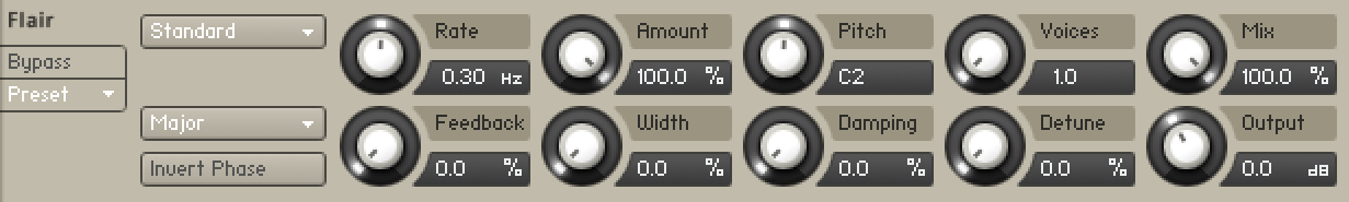 |
Mode: Switches between three flanger modes (Standard, Thru Zero, Scan):
Standard: In this mode, each flanger voice behaves like a basic flanger effect, creating harmonically related peaks and notches in the frequency spectrum.
Thru Zero: In this mode, each flanger voice is duplicated. The duplicated instances of the flanger voices are excluded from the modulation and thus rest at their respective base pitch. When modulation is introduced by increasing Amount, the flanger voices shift against the duplicated instances in time. This creates the strong thru zero flanging effect with its characteristic signal cancellation, similar to the flanging effect originally created with two tape machines.
Scan: In this mode, instead of adding the flanger voices to form a chord, Voices scans through them one after the other. This is similar to how an arpeggiator on a keyboard plays the notes contained in a chord as a sequence. The Scan Mode selector below the Mode menu allows you to choose from three different waveforms for the modulation: Triangle, Sawtooth Up, and Sawtooth Down.
Offset: Adds a frequency shift to the duplicated flanger voices in Thru Zero mode, changing their position relative to the center of modulation. This results in rhythmical variations of the flanging effect. Offset also enables you to reduce the amount of signal cancellation when there is no modulation (Amount set to 0%).
Chord: Sets a chord that defines the harmonic relationship between the four Voices.
Invert Phase: Swaps the position of the peaks and notches in the frequency spectrum by inverting the effect signal. When activated, the perceived pitch of the flanger voices is one octave lower. In Thru Zero mode, enabling Invert creates strong signal cancellations at the center of modulation, which can lead to interesting rhythmical effects.
Rate: Adjusts the frequency of the modulation applied to Pitch. The modulation effect becomes more pronounced as Amount is increased. When LFO Sync is activated, modulation is synchronized to the host and the Rate knob is replaced by the LFO Sync controls: The Numerator (a) and Denominator (b) set the speed of modulation in musical notes relative to the host tempo. The Numerator sets the number of notes, while the Denominator sets the note value. The Sync Mode (c) sets the time value, or subdivision, for the chosen note value. For example, 1|4 in Sync Mode Straight means that the modulation repeats its cycle after one quarter note, and 3|2 in Sync Mode Triplet means that the modulation repeats its cycle after three half note triplets.
Feedback: Adjusts the level of the feedback signals from the outputs of the flanger voices to their inputs, creating a more resonant and metallic sound.
Amount: Adjusts the amount of modulation applied to Pitch, adding movement to the flanging effect.
Width: Duplicates the flanger voices internally and pans them in opposite directions. A wide and lively stereo image is created by adding a phase offset to the modulation applied to Pitch between the left and right stereo channels. Additionally, a special type of cross-feedback is introduced, further animating the stereo image as Feedback is increased.
Pitch: Adjusts the fundamental frequency of the first flanger voice in semitones, effectively shifting the peaks and notches of all flanger voices in the frequency spectrum.
Damping: Attenuates the high frequency content of the feedback signals from the outputs of the flanger voices to their inputs, allowing for soft sounds even at high Feedback settings.
Voices: When Mode is set to Standard or Thru Zero, Voices fades from one to four flanger voices. The additional flanger voices are added in harmonic intervals, forming a chord as set with Chord. When Mode is set to Scan, Voices scans through the four flanger voices one after the other by blending between the first and the second flanger voice, then the second and the third flanger voice, and so on.
Detune: Alters the pitch of each individual flanger voice in a range of approximately +/- 60 cent. This creates a rich and lively sound similar to the effect of detuning oscillators on a synthesizer. Detune is especially useful when Chord is set to Unison.
Mix: Blends between the input signal and the effect signal. When the knob is turned fully left, only the dry input signal is heard.
Output: Adjusts the module’s output level.
Freak
Freak combines different amplitude modulation techniques and is based on a model of an analog diode ring circuit that produces rich harmonic overtones and textures. In addition to a wide range of harmonic transformations, its three FX Modes facilitate special applications like AM radio simulation (Radio mode), tremolo and distortion (Oscillator mode), as well as gating (Sidechain mode).
In all three FX Modes the Type control smoothly morphs between basic amplitude modulation (0%), ring modulation (50%), and frequency shifting (100%), while Harmonics and Feedback allow you to control the intensity of the effect. Mix blends between the dry and the wet signal and Output controls the volume of the module in dB. The controls on the left side are specific to each individual mode and are described in detail below.
Displayed here is Freak in Oscillator mode.
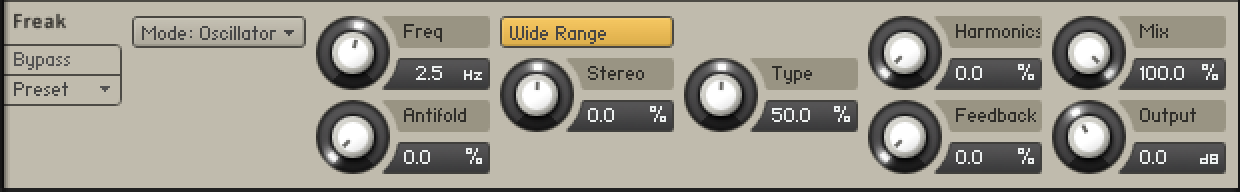
In Radio mode, Freak emulates the behavior of so-called demodulation circuits in old AM radios, allowing you to create the effect “of dialing in the frequency of a specific radio station. This emulation complements the amplitude modulation techniques available via the Type control. This mode uses a sine wave signal as the modulation source.
Tuning: Emulates the effect of tuning an old AM radio. In center position, the best possible tuning is achieved. As you move the control away from center position, the amount of radio interference increases.
Demod: Switches between emulations of two different demodulation circuits. When activated, a product demodulation circuit is used, producing an aggressive sound. When deactivated, an envelope demodulation circuit is used, recreating the sound of an old AM radio.
Width: Adjusts the amount of filtering applied to the signal by changing the bandwidth of the band-pass filter used in the demodulation circuit. Low settings result in a filtered and slightly resonant sound. High settings reduce the filtering effect while adding more noise to the signal.
Carrier: Adjusts the frequency of the carrier used in the demodulation circuit, controlling the quality of the radio transmission. The quality improves as you increase the frequency.
Gate: Switches the noise gate on or off. When activated, noise from the demodulation circuit is only passed through if an input signal is present. When deactivated, the noise is constantly passed through, allowing you to use Freak as a flexible noise source. The amount of noise can be adjusted with the Feedback control.
In Oscillator mode, you can explore the pure sound of the three different amplitude modulation techniques available via the Type control. This modes uses a sine wave signal as the modulation source.
Freq: Adjusts the rate of the internal sine wave modulation used by the three different amplitude modulation techniques available via the Type control. When Type is set to amplitude (0%) and ring (50%) modulation, this allows you to change the frequency of the sidebands created in the frequency spectrum. When Type is set to frequency shifting (100%), the modulation rate equals the amount by which the input signal’s frequency content is shifted in the frequency spectrum. The Freq control is bipolar, meaning that both positive (non-inverted) and negative (inverted) modulation can be applied. The range of the Freq control can be set with the Range button.
Wide Range: Sets the range of the Freq control. When activated, Freq has a coarse range of -5000 Hz to +5000 Hz. When deactivated, Freq has a fine range of -200 Hz to +200 Hz. This gives you full control over applications that require fine adjustment of the modulation rate below the audio spectrum (< 20 Hz).
Stereo: Creates a wide stereo image by adding a phase offset to the modulation applied to the left and right stereo channels.
Antifold: Reduces the amount of sidebands folding over 0 Hz, producing a cleaner sound in the low-frequency spectrum. By increasing Antifold, thinner sounding distortion effects with a less tonal quality can be achieved.
Sidechain mode opens up the amplitude modulation techniques available via the Type control for experimentation with a variety of modulation sources. It is possible to modulate the input signal with itself, or to use any external signal as the modulation source by feeding it into the plug-in’s sidechain input. Additionally, the modulation signal can be processed with an envelope follower that smoothes out the signal contour.
Contour: Blends between the direct signal from the modulation source and the signal processed by the envelope follower. This enables you to adjust how much the envelope follower affects the contour of the modulation signal.
Release: Adjusts the attack and release times of the envelope follower. At low settings, the envelope follower quickly adapts to the contour of the modulation signal. At high settings, it responds slowly and smoothes out the contour of the modulation signal.
BP Filter: Switches the band-pass filter applied to the modulation signal on or off. The filter’s cutoff frequency can be adjusted with the BP Freq control.
BP Freq: Adjusts the cutoff frequency of the band-pass filter applied to the modulation signal, reducing its frequency content to a specific band. When combined with the envelope follower, BP Freq can be used to make the envelope follower respond to specific components of the modulation source.
Phasis
Phasers are used to enrich sounds by adding spectral animation and complex filtering. They are based on a series of all-pass filters, with built-in modulation of the all-pass filter’s frequencies. The all-pass filters produce peaks and notches in the frequency spectrum that can be altered over time. This way a phaser transforms and animates the harmonic structure of the sound. The results range from classic Krautrock guitars to psychedelic FX sounds.
As one of the most commonly used guitar and studio effects, various implementations of the phaser have found their way into studio rack processors and guitar pedals. Phasis is a new take on the concept with additional features that have been carefully chosen to allow for more sophisticated and extreme sounds than possible with common phasers, while staying true to the ease of use and clarity associated with these devices.
Phasis features a scalable amount of all-pass filters, producing up to twelve pairs of peaks and notches in the frequency spectrum. The input signal’s stereo image is preserved, however additional processing can be applied to widen the sound (Stereo parameter). The internal modulation system can not only alter the relative center frequency of all peaks and notches at the same time (Center parameter), but also their spacing to each other (Spread parameter), allowing for vowel filtering effects. Further expanding on the original concept of a phaser, ULTRA mode extends the frequency ranges of the all-pass filters as well as the modulation to audio rates, further expanding on the filtering capabilities of Phasis create sounds reminiscent of FM synthesis.
Phasis contains the following controls:
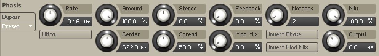 |
Rate: Adjusts the frequency of the modulation applied to Center and Spread. The modulation effect becomes more pronounced as the Amount is increased. To synchronize the time to your host or master editor tempo, click the Rate unit display (Hz) and chose a note length value from the drop down menu.
ULTRA mode: Extends the parameter ranges for Rate and Center, allowing for more extreme modulation frequencies across a wider frequency range. By increasing Rate to audio frequencies, you can add new harmonic content to the input signal, similar to the sounds possible with FM synthesis.
Amount: Adjusts the amount of modulation applied to Center and Spread, adding movement to the phasing effect. The modulation can be distributed between the two parameters with the Mod Mix slider.
Center: Shifts the peaks and notches in the frequency spectrum by changing the frequencies of the all-pass filters that create the phasing effect (relative to the Center frequency).
Stereo: Creates a wide and lively stereo image by adding a phase offset to the modulation applied to Center and Spread between the left and right stereo channels. In center position, the phasing effect does not alter the stereo image. When turning the knob to the left, the phasing effect appears to move from right to left. When turning the knob to the right, the phasing effect appears to move from the left to right. Stereo does not have an effect if Amount is set to 0.
Spread: Adjusts the density of the peaks and notches in the frequency spectrum. Turning the knob left moves the peaks and notches closer to each other. Turning the knob right moves the peaks and notches further apart from each other.
Feedback: Adjusts the amount of feedback, or resonance, applied to the all-pass filters that create the phasing effect. Turning the knob right will increase the Feedback, making the peaks and notches in the frequency spectrum more pronounced.
Mod Mix: Distributes the modulation between Center and Spread. Moving the slider to the left increases the amount of modulation applied to Center, moving the slider to the right increases the amount of modulation applied to Spread. In the middle position, the amounts of modulation applied to both Center and Spread are the same.
Notches: Sets the number of peaks and notches in the frequency spectrum.
Invert Phase: Inverts the polarity of the modulation applied to Spread, hence reversing its effect in relation to the modulation applied to Center.
Invert Mod Mix: Swaps the position of the peaks and notches in the frequency spectrum by inverting the effect signal.
Mix: Blends between the input signal and the effect signal. When the knob is turned fully left, only the dry input signal is heard.
Output: Adjusts the module’s output level.
Ring Modulator
Ring Modulator is an effect based on ring modulation, a special type of amplitude modulation. It produces sidebands in the frequency spectrum that break up the harmonic structure of the sound and give it a metallic sounding character. When using a low-frequency modulation signal, you can achieve tremolo effects. Additionally, the FM control enables you to apply phase modulation to the input signal (FM).
Ring Modulator contains the following controls:
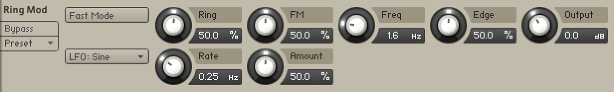
Fast Mode: Switches between two frequency ranges for the internal modulation oscillator. When activated, the effect produces sidebands in the frequency spectrum. When deactivated, it produces tremolo effects.
LFO: Sine/Square: Switches the LFO’s waveform between sine and square, producing either soft or sudden changes of the internal modulation oscillator's frequency.
Ring: Adjusts the amount of ring modulation applied to the input signal using the internal modulation oscillator.
Rate: Adjusts the frequency of the LFO that can be used to apply modulation to the frequency of the internal modulation oscillator. To synchronize the rate to your host or Master Editor tempo, click the Rate parameter’s unit display and choose a note length value from the drop-down list.
FM: Adjusts the amount of phase modulation applied to the input signal using the internal modulation oscillator.
Amount: Adjusts the amount of modulation applied to the frequency of the internal modulation oscillator using the LFO.
Freq: Adjusts the frequency of the internal modulation oscillator, effectively moving the sidebands in the frequency spectrum. The frequency range depends on the setting of the Fast Mode switch.
Edge: Changes the waveform of the internal modulation oscillator. Turning the control to the right adds harmonics, resulting in a more aggressive sound of the ring modulation.
Output: Adjusts the module’s output level.
Rotator
The Rotator effect realistically simulates the sound of rotating speaker cabinets, which are commonly associated with drawbar organs that became popular in rock music of the 60s and 70s. Although the effect is almost intrinsically tied to "the" prototypical drawbar organ sound, it works equally well on guitars, synth pads, and a wide range of other sounds.
Rotator contains the following controls:
 |
Speed: Although this parameter appears as a knob in order to facilitate automating, it really only has 2 positions — Slow and Fast. A change of this setting realistically simulates the acceleration or braking of the rotor.
Acceleration and Brake Speed (horizontal faders next to the Speed control): These adjust how quickly the rotors of the treble (upper fader) and bass (lower fader) parts of the cabinet will react to speed changes. At the rightmost position, the respective speaker will change its speed instantly, while it will take a long time to reach its designated speed with the fader at the leftmost position.
Balance: Controls the relative levels of the cabinet’s treble and bass parts.
Distance: Controls the simulated distance between the cabinet and the pickup microphones. A closer distance results in a wider stereo panorama.
Vibrato/Chorus
Vibrato/Chorus models the sound of the vibrato and chorus effects found on a classic electric organ. The effects were originally produced by an innovative circuit that combined electronic and mechanical components, producing an incredibly rich sound.
Vibrato/Chorus contains the following controls:

Depth: Sets the intensity of the effect by selecting one of six modes. The intensity increases with every mode from left to right. Modes IV, V, and VI require more processing power.
Color: Selects one of three different modes that determine the basic sound character of the effect. Each mode has a distinct frequency response and different flavor of modulation.
Rate: Adjusts the frequency of the modulation. When Sync is activated, Rate is set in note lengths relative to the tempo of the Metronome.
Blend: Blends between the vibrato and the chorus effect.
Width: Adjusts the width of the stereo widening effect.
Mix: Blends between the input signal and the effect signal.
Output: Adjusts the module’s output level in dB.
Legacy Chorus
The Chorus adds depth and richness to the audio signal by layering the original signal with a detuned copy of itself. Separate LFOs with an adjustable phase relationship detune each stereo channel independently for creating wide panorama effects.
Chorus contains the following controls:

Depth: Adjusts the range of modulated detuning. Higher values give a more pronounced chorusing effect.
Speed: Adjusts the LFO speed. To synchronize the speed to your host or Master Editor tempo, click the Speed parameter’s unit display and choose a note length value from the drop-down list.
Phase (0 to 90 degrees): Imparts an LFO phase difference between the left and the right stereo channel. This can considerably increase the width of the output signal’s stereo base.
Return (visible when used as a send effect): Adjusts the module’s return level.
Dry and Wet sliders (visible when used as an Instrument insert effect): Adjusts the respective levels of the original and processed signals. Note that the typical chorus effect is created by the combination of both signals, so setting these to the same levels results in the most pronounced effect.
Legacy Flanger
This module splits the audio signal up and delays one version in relation to the original signal. By modulating the delay time, as well as feeding an adjustable amount of the output signal back into the input, the Flanger creates a characteristic “whooshing” sound. Just like the Phaser module, the Flanger uses a separate LFO for each stereo channel, with the phase relationship between both LFOs being adjustable.
Flanger contains the following controls:

Depth: The amount of LFO modulation. Higher values cause the flanging effect to sweep over a wider range.
Speed: Adjusts the LFO speed. To synchronize the speed to your host or Master Editor tempo, click the Speed parameter’s unit display and choose a note length value from the drop-down list.
Phase (0 to 90 degrees): Imparts an LFO phase difference between the left and the right stereo channel. This can considerably increase the width of the output signal’s stereo base.
Colour: Adjusts the delay line’s range of operation and, consequently, the color of the flanging effect. Small values result in short modulated delay times, making the Flanger sound more like a phaser.
Feedback: Feeds a certain amount of the delayed signal back into the module’s input, thereby creating a more pronounced effect.
Return (visible when used as a send effect): Adjusts the module’s return level.
Dry and Wet sliders (visible when used as an Instrument insert effect): Adjusts the respective levels of the original and processed signals. Note that the typical flanging effect is created by the combination of both signals, so setting these to the same levels results in the most pronounced effect.
Legacy Phaser
This effect continually changes the phase relationships in your signal with an all-pass filter. This results in a comb filtering effect, which attenuates some frequencies while boosting others. The sound is similar to that of a flanger but in a more subtle manner.
Phaser contains the following controls:

Depth: The amount of LFO modulation. Higher values cause the Phaser effect to sweep over a wider frequency range.
Speed: The LFO modulation speed. To synchronize the speed to your host or Master Editor tempo, click the Speed control’s unit display and choose a note length value from the drop-down list.
Phase (0 to 90 degrees): Imparts an LFO phase difference between the left and the right stereo channel. This can considerably increase the width of the output signal’s stereo base.
Feedb.: This control adjusts the emphasis of the peaks and notches that the comb filter effect imparts on the signal.
Return (visible when used as Send Effect): Adjusts the return level of the module’s output signal.
Dry and Wet sliders (visible when used as an Instrument Insert Effect): Adjusts the respective levels of the original and processed signals. Note that the typical phasing effect is created by the combination of both signals, so setting these to the same levels results in the most pronounced effect.
Delays
Delay effects include the Replika Delay and Legacy Delay.
PsycheDelay
Psyche Delay is a stereo delay effect that produces a range of atmospheric ambient echoes and reverse effects reminiscent of the so-called backwards tape sound of the 1960s.
PsycheDelay contains the following controls:
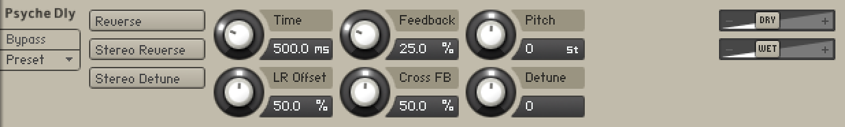
Reverse: Reverses the playback of subsequent delay repeats.
Stereo Reverse: Reverses the playback of subsequent delay repeats on one of the stereo channels.
Stereo Detune: Adjusts the pitch of the echo repeats on the left stereo channel in the range of -50 to +50 cents. Combined with feedback and cross-feedback you can use this to create progressively detuned echo cascades.
Time: The delay time in milliseconds. To synchronize the time to your host or Master Editor tempo, click the Speed parameter’s unit display and choose a note length value from the drop-down list.
LR Offset: Adjusts the amount of time deviation between the two stereo channels, resulting in wide stereo echos.
Feedback: Adjusts the amount of feedback. Turning Feedback to the right increases the amount of delay repetitions.
Cross FB: Adjusts the amount of feedback from the left to the right stereo channel and vice versa, creating a more complex stereo echo pattern.
Pitch: Adjusts the pitch of the echo repeats in the range of -12 to +12 semitones. Combined with feedback you can use this to create progressively harmonized echo cascades.
Detune: Fine-tunes the pitch of the echo repeats in the range of -50 to +50 cents.
Dry and Wet sliders (visible when used as an Instrument insert effect): Adjusts the respective levels of the original and processed signals. In common scenarios, the delayed signal is mixed in at a lower level than the direct signal.
Replika Delay
This delay module is based on Native Instruments’ dedicated Replika XT delay plug-in. It features five different modes - Modern, Analog, Tape, Vintage and Diffusion - that add distinct colour to your sound. All modes offer controls for time, feedback level, a low cut filter, a high cut filter, and ping pong effect. Each mode also provides a unique range of parameter controls that allows you to tailor the effect to your specific needs.
Modern mode is a clean delay, with saturation and filter controls that allow you to add warmth and colour to your sound. It is a pristine and transparent delay, well-suited to acoustic instruments like guitar and piano. When changing the delay time, pitch stays constant. Analog mode offers four Bucket Brigade delay models that replicate the character sound of BBD chips. From subtle distortion and warmth, to clean, smooth sounds, each model emulates desired characteristics of classic analog delay units. Tape mode reproduces the sound of tape delay, modelled on the physical mechanisms that make up early tape machines. Controls for Tape Age, Flutter and Saturation allow you manipulate the noise, hiss and colour of the effect. Vintage mode emulates the sound of early digital delay units. Select between four quality levels that model the behaviour of vintage delays with a limited sample memory size. Increasing the delay time causes the sampling rate to decrease, introducing audio artefacts. The sample quality and interpolation vary for each of the four quality levels. Diffusion mode can produce a standard delay effect, but it is best used for its huge, diffusion-based reverb sound. Thicken the density of delay repeats with the Dense, Modulation and Size controls to create a full sounding reverb effect. This mode is ideal for ambient music and sound design.
Replika Delay contains the following controls:
 |
Mode: Selects one of five delay modes (Modern, Analogue, Tape, Vintage, Diffusion).
Time: Adjusts the delay time in milliseconds. To synchronize the time to your host or Master Editor tempo, click the Time control’s unit display (ms) and choose a note length value from the drop-down menu.
Feedback: Adjusts the level of the signal that is fed back to the delay's input. Increasing Feedback adds delay repeats. Levels above 100% create swelling echo repeats up to self-oscillation.
Low Cut: Cuts low-frequency content in the feedback path of the delay with a non-resonant filter. Turned fully counter-clockwise, the filter is off.
High Cut: Cuts high-frequency content in the feedback path of the delay with a non-resonant filter. Turned fully clockwise, the filter is off.
Ping Pong: Switches the Ping Pong effect on and off. When on, the delay repeats are panned hard left and right in an alternating pattern.
Stereo: When activated, the modulation between the left and the right channel is offset in time, resulting in a wide stereo effect. When deactivated, the modulation affects both channels in the same way.
Saturation: Adds tube-like saturation at the delay input. Turning it clockwise pushes the sound from subtle warmth to overdrive. Turned fully counter-clockwise, the saturation is bypassed.
Depth: Adjusts the amount of modulation applied to the delay time.
Rate: Adjusts the speed of the delay time modulation.
Quality: Selects one of four quality settings for the delay: Crunch (0-24%), Low (25-49%), Medium (50-74%), High (75-100%).
Noise: When activated, tape hiss is added to the delay signal. When deactivated, no tape hiss is added. The amount of tape hiss depends on the setting of the Tape Age control.
Tape Age: Enhances the characteristics of an aging tape, including limited high-frequency response. When the Noise button is activated, Tape Age also adjusts the amount of tape hiss added to the signal.
Flutter: Increases the effects introduced by mechanical imperfections of the tape delay’s motor and tape transport, resulting in pitch variations over time.
BBD type: Selects one of four BBD delay models (from left to right, Grunge, Dark, Warm, Clean). The character ranges from subtle filtering and distortion to a highly degraded sound.
Amount: Adjusts the amount of diffusion applied to the delay signal, resulting in a reverb effect. High settings can make the delay appear out of sync.
Dense: Switches between two density settings for the reflection pattern of the effect.
Modulation: Sets the depth and speed of modulation applied to the diffusion, shifting the timing and pitch of the reflections for a wide reverb effect.
Size: Adjusts the swell, reflection pattern and decay of the reverb effect, giving the impression of different sized spaces.
Twin Delay
Twin Delay combines two parallel delay channels for advanced stereo effects. The two delays are dedicated to the left and right stereo channel, respectively. You can use them to create rhythmic echoes that bounce through the stereo image.
Twin Delay includes the following controls:
Predly L/R: Adjusts the duration of the initial delay added to the channel. This predelay is independent of the Time control and does not affect the delay repeats. To achieve classic ping-pong echoes, set the same Time for both channels and increase Predly on one of them. To synchronize the time to your host or master editor tempo, click the predelay unit display (ms) and chose a note length value from the drop down menu.
Time L/R: Adjusts the delay time in milliseconds. To synchronize the time to your host or master editor tempo, click the Time unit display (ms) and chose a note length value from the drop down menu.
Feed L/R: Adjusts the amount of feedback. Turning Feed to the right increases the amount of delay repetitions.
Level L/R: Adjusts the output level of the delay channel.
Cross FB: Adjusts the amount of cross-feedback, which feeds the left channel output back into the right channel input and vice versa.
Width: Adjusts the stereo image of the delay signal. At center position, the signal is mono. Turning the control to the right increases the width of the stereo image. Turning the control to the left increases the width of the stereo image and flips the left and right stereo channel.
DRY/WET: These sliders adjust the amount of unprocessed (DRY) and processed (WET) signal that is send to the output.
Legacy Delay
This module offers a delay line that can optionally be synced to the tempo and provides an adjustable feedback level, a low-pass filter, and a pan control for ping-pong echo effects. If you don’t use the tempo syncing feature, the available delay range is 5 to 2900 ms. Delay times lower than 20 ms are not discernible as delays, but can produce interesting comb filtering effects.
Legacy Delay contains the following controls:

Time: The delay time in milliseconds. To synchronize the time to your host or Master Editor tempo, click the Speed parameter’s unit display and choose a note length value from the drop-down list.
Damping: Attenuates high frequencies in the delayed signal. Turning this control clockwise will increase the damping effect. If you have set a feedback level, the signal will gradually lose more high frequency content with each repetition.
Pan: Setting a value higher than 0 creates a panning effect, which alternates echos between the left and the right side of the stereo panorama — this is affectionally called a ping-pong delay. Higher values will result in wider panning; at 100, signals alternate between the far left and far right channel.
Feedb. (feedback): Controls the amount of the output signal that’s being fed back into the input of the delay line, thereby creating a series of echos that gradually fade into silence.
Return (visible when used as a send effect): Adjusts the module’s return level.
Dry and Wet sliders (visible when used as an Instrument insert effect): Adjusts the respective levels of the original and processed signals. In common scenarios, the delayed signal is mixed in at a lower level than the direct signal.
Reverbs
Reverb effects include the Convolution, Plate Reverb, Reverb and Legacy Reverb.
Convolution
Convolution is a sophisticated mathematical process that, technically speaking, allows you to replicate the acoustical behavior of a linear system — such as a room, a speaker or a hardware reverb unit — for use with your own signals. To accomplish this, a short audio recording of a wide-band signal played through the system is fed into the convolution processor. This recording is usually a normal audio file, called an impulse response.
Convolution is best known among users as a method for achieving highly realistic reverbs; it works just as well for simulating the characteristic resonances of speaker cabinets and other loudspeakers, though.
Kontakt’s Convolution processor is somewhat unique in that it fully supports a multi-channel signal flow, allowing you to use surround impulse responses. It can be used within the Instrument Insert Effects and the Instrument Send Effects chains, or as an Output effect. Kontakt includes an extensive library of impulse responses, which range from recordings of real rooms and speaker cabinets to synthetic impulse responses that are well-suited for special effects, but you can just as easily use third-party impulses in WAV format.
Convolution contains the following controls:
Impulse Window: This window provides a display of the currently loaded impulse response and, if active, the Volume Envelope. You can drag impulse responses from the library into this window to load them — this will keep your other settings intact. The row at the top displays the filename of the loaded impulse response, as well as its bit depth, sample rate, and number of channels. Just like in the Mapping Editor and Wave Editor, hovering your mouse pointer over the filename will show the full path to the file.
Pre Dly.: Just like the Reverb module’s parameter of the same name, this control introduces a short amount of delay between the direct signal and the convolution output. This is useful when used with reverb responses to simulate the reverberation of big rooms, where a short delay occurs between the direct sound and the first reflections from distant walls.
Return (visible when used as a send effect): Adjusts the module’s return level.
Dry and Wet sliders (visible when used as an Instrument insert effect): Adjusts the respective levels of the original and processed signals. In common scenarios, the reverb signal is mixed in at a lower level than the direct signal.
Latency: Adjusts the module’s latency setting in five steps (1.5, 2.9, 5.8, 11.6, and 23.2 ms). If you hear crackles or other artifacts, you can try to increase this value, which will result in Kontakt’s overall latency being increased (and thus all signals being delayed). If you don’t want this, you can disable the latency compensation by activating the last entry in this menu. This way, the overall latency won’t be increased, but the wet signal of the Convolution processor will be delayed in relation to the dry signal (which actually can work just fine with reverbs).
S.Rate: Allows you to divide the sample rate in nine steps (1/1, 1/1.5, 1/2, 1/2.5, 1/3, 1/4, 1/6, 1/8, and Auto). If the Preserve Length button is not activated, changing the sample merely changes the playback speed of the impulse response, resulting in longer reverb trails and changed frequency characteristics. Activating Preserve Length will keep the reverb trail intact, but lower the sampling rate at which the convolution process takes place, thereby reducing the CPU usage along with the quality.
Reverse Button: Reverses the impulse response for special effects.
Auto Gain: If this button is active, the processor will keep the overall level constant when parameters are adjusted that would otherwise affect the level. If you turn this off, be sure to monitor at low levels as you make adjustments, as volume changes can be drastic — take care of your ears!
VolumeEnvelope: This feature allows you to change the volume characteristic of the impulse response to your needs. When activated, a graphically editable 8-segment envelope will be drawn on top of the waveform display in the impulse response window.
Early / Late: These mode buttons switch the 3 knobs below between affecting the early reflections and the trail part of the impulse response.
IR Size: Artificially compresses or stretches the impulse response in time.
HighPass: Adjusts the cutoff frequency below which the signal’s frequency content will be attenuated.
LowPass: Adjusts the cutoff frequency above which the signal’s frequency content will be attenuated.
Plate Reverb
This new effect module emulates a plate reverb. Plate reverb was developed as an early method of generating an artificial reverb effect. A vibrating sheet of metal is employed to simulate reflection patterns in acoustical spaces. Since the sheet of metal vibrates across a two-dimensional plane, the echo density is higher and more evenly distributed than in a three-dimensional space. It is a good choice if you want to brighten a sound source. Plate reverb has a smooth reverb tail, allowing you to lengthen a sound without pushing it back in the mix. For this reason plate reverbs are most commonly used on vocals and snare drums. The Damping control affects the overall tone, so applying it to a bright source warms the sound.
Plate Reverb contains the following controls:
 |
Pre Delay: Introduces a short amount of delay before the reverb takes effect.
Decay: Adjusts the duration of the reverb effect.
Low Shelf: Attenuates or amplifies the low-frequency content of the reverb signal.
High Damp: Adjusts the damping of high-frequency content of the reverb signal.
Stereo: Controls the stereo image of the reverb effect. Higher values result in a wider stereo image.
Raum
Raum offers three different reverb algorithms that cover an extremely wide range of reverb sounds. Each of them is based on a different paradigm: Grounded focuses on rooms, Airy on halls, and Cosmic on abstract spaces. However, the individual parameters like Size and Decay are designed in such way that each of the algorithms can be used to create anything from tight ambiences to otherworldly soundscapes, while maintaining the basic character of its paradigm.
Raum includes the following controls:
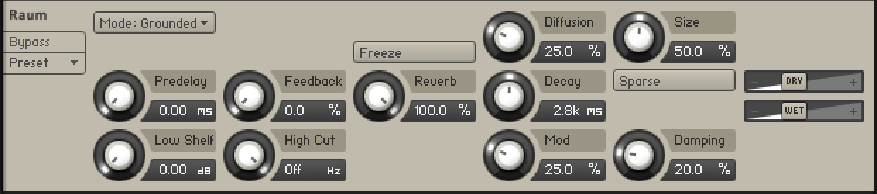
Mode: Selects one of three different reverb algorithms, from rooms (Grounded), to halls (Airy), to abstract spaces (Cosmic).
Predelay: Adjusts the duration of the predelay, which is the time it takes for the reverb effect to set in. By increasing the predelay, you can add separation between the input signal and the reverb signal.
Feedback: Adjusts the level of the feedback signal from the output of the predelay to its input, effectively increasing the number of delay repetitions. Turning Feedback to the right creates echo effects that can be further processed using the selected reverb algorithm. When Feedback is set to 100%, you can achieve infinite delay repeats and therefore use the predelay as a looper. A built-in limiter controls the level when high feedback settings are used with loud input signals.
Low Shelf: Attenuates low-frequency content of the reverb effect and the predelay's feedback signal by applying a low-shelf filter in the range of 0 dB to -24 dB. Turning the control to the left decreases the attenuation. Turning the control to the right increases the attenuation. Turning the control fully to the left switches the filter off.
High Cut: Attenuates high-frequency content of the reverb effect and the predelay's feedback signal by applying a high-cut filter in the range of 90 kHz to 1 kHz. Turning the control to the left increases the attenuation. Turning the control to the right decreases the attenuation. Turning the control fully to the right switches the filter off.
Freeze: Holds the reverb's sound content for as long as the function is activated. The Freeze function is available for the Grounded and Airy algorithms. Switching is optimized for smooth transitions without clicks, and you can still use the Size control to manipulate the sound. This makes the Freeze function an excellent tool for live performance and automation.
Reverb: Adjusts the amount of reverb added to the effect signal.
Diffusion: Adjusts the texture of the reverb reflections. Turning the control to the right softens the early reflections and produces a smooth onset of the reverb.
Size: Adjusts the swell and reflection pattern of the reverb effect, creating the impression of differently sized spaces. Turning the control to the right changes the size from small to large.
Sparse: Switches between two basic density modes for the reflection pattern of the reverb effect, Sparse and Dense. When enabled, Sparse produces dispersed and clearly discernible reflections. When disabled, Dense produces a more uniform reverb tail.
Decay: Adjusts the length of the reverb, or reverb time. Turning the control to the right changes the reverb time from short to long.
Damping: Adjusts the tonal quality from bright to dark. Turning the control to the right attenuates the reverb's high-frequency content.
Mod: Adjusts the amount of movement added to the reverb sound by changing internal parameters of the reverb over time. Turning the control to the right changes the movement of the reverb from lush to strongly detuned sounds.
DRY/WET: These sliders adjust the amount of unprocessed (DRY) and processed (WET) signal that is send to the output.
Reverb
This algorithmic reverb offers Room and Hall modes. Room mode generates a natural reverb with strong initial reflections and a quick decay. You can use this to simulate the natural sound of a small acoustic space. With a faster reverberation time, it is particularly suited to drums and guitars.
Hall mode emulates the immensity of a large hall space, with a warm and rich sounding reverb. This can be used to replicate a vast, natural space. The large reverberation and long decay time make it a great tool to experiment with on a variety of sounds. In either mode, you can modulate the Room Size and Pre Delay parameters to create dynamic special effects.
Reverb contains the following controls:
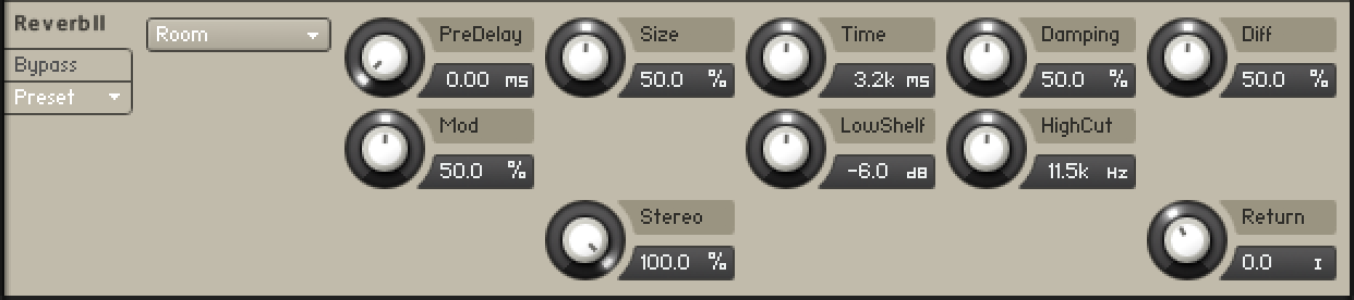
Mode: Selects one of two reverb modes (Room and Hall). Room is suited to drum and percussive sounds. Hall has a spacious and natural character and is particularly suited to tonal sounds.
Pre Delay: Introduces a short amount of delay before the reverb takes effect.
Size: Adjusts the size of the room simulated by the reverb effect. Higher values replicate larger rooms.
Time: Adjusts the duration of the reverb effect.
Damping: Adjusts the amount of absorption in the room simulated by the reverb effect. Higher values result in more absorption.
Diffusion: Adjusts the density of the reflections in the room simulated by the reverb effect.
Modulation: Adjusts the amount of modulation applied to the reverb effect. Turned fully counter-clockwise, no modulation is applied.
Low Shelf: Attenuates or amplifies the low-frequency content of the reverb signal.
High Cut:: Cuts the high-frequency content of the reverb signal.
Stereo: Controls the stereo image of the reverb effect. Higher values result in a wider stereo image.
Legacy Reverb
This module simulates the natural reverberation that occurs when a sound source is placed in an acoustic environment, thus adding a feeling of spaciousness to the sound.
Legacy Reverb contains the following controls:

Pre Dly.: Introduces a short delay between the direct signal and the reverb trail build-up. This corresponds to the natural reverberation behavior of large rooms, where a short time elapses before the first reflection of a sound wave returns from a wall.
Size: Adjusts the size of the simulated room. This affects the duration of the reverb trail.
Colour: This control allows you to adjust the construction material of the simulated room and, consequently, the color of the reverb trail. Low values simulate softer surfaces like wood, while high values simulate the reflection behavior of hard surfaces like concrete.
Damping: Sets the amount of simulated absorption that takes place in rooms due to furnishings, people, or acoustic treatments affecting the reflection behavior.
Stereo: Higher values increase the stereo base width of the output signal. Lower values simulate a closer distance to the sound source.
Return (visible when used as a send effect): Adjusts the module’s return level.
Dry and Wet sliders (visible when used as an Instrument insert effect): Adjusts the respective levels of the original and processed signals. In common scenarios, the reverb signal is mixed in at a lower level than the direct signal.
Spatial
Stereo Modeller
This module allows you to control the width of your signal’s stereo base, change the panning, and create a pseudo-stereo signal from mono sources.
Stereo Modeller contains the following controls:

Pseudo Stereo: When activated, the module uses a pseudo-stereo algorithm to create a stereo signal from a mono source. This feature should only be used with mono signals and tends to create mono-incompatible sounds, which can disappear from a mix when it’s being played back in mono.
Spread: Reduces or expands the signal’s stereo base. Turning the knob far left, will sum the stereo signals to mono. Turning the knob right to produce positive values will result in an artificial widening of stereo sources.
Pan: This control allows you to place your signal within the stereo field. It works exactly like the Pan control of the Amplifier module.
Output: Adjusts the module’s output level.
Stereo Tuner
Stereo Tuner is a widening effect. It produces a wide and lively stereo image.
Stereo Tuner contains the following controls:

Spread: Adjusts the stereo width from mono to full stereo.
Drift: Adjusts stereo detuning of the input signal. The left and right stereo channels are tuned at different frequencies to create a wide stereo image.
Split: Adjusts the crossover frequency of the effect. Frequency content below this frequency remains unaltered.
Mix: Blends between the input signal and the effect signal. When the knob is turned fully left, only the dry input signal is heard.
Output: Adjusts the module’s output level.
Surround Panner
This module provides extensive and powerful surround mixing and automation capabilities to Group signals. It works with a multitude of input and output channel configurations, ranging from mono up to 16-channel surround sound, and allows you to place input signals as sound sources on a spatial plane, move them either manually or via automation, and simulate a range of natural dampening and doppler effects which occur when sound sources are being moved around the listener.
Surround Panner contains the following features and controls:
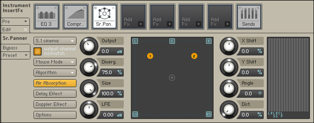
Output: Adjust the module’s output level.
Divergence: Adjusts the amount of distance-dependent level changes and, consequently, the directional focus of sound sources on the surround plane. Setting the knob to 0% will result in constant levels regardless of positioning.
Size: Adjusts the size of the surround plane. When set to 100%, the area surrounded by the speakers will fill out the plane window, so it won’t be possible to move a sound source beyond the limits of the speakers. Turning the knob counter-clockwise will “zoom out” and allow you to place sources outside the area of the speaker arrangement.
LFE: If the currently selected output configuration includes a low frequency effects (LFE) channel, this control adjusts its output level. Note that the LFE channel signal is derived from a sum of all input signals via a frequency crossover; the frequency at which the split occurs can be set in the options dialog.
X Shift: Imparts a constant offset on the X positions of all sound sources.
Y Shift: Imparts a constant offset on the Y positions of all sound sources.
Angle: Rotates all sound sources around the center point.
Distance: Adds a constant offset to the distances of all sound sources from the center point.
Meter: The output levels of all channels in the currently selected Surround Format are displayed here.
Menus and Buttons
The following menus are available:
Surround Format: This drop-down menu selects the output format of the module. Options range from simple speaker-subwoofer splits (1.1) up to 16-channel surround formats, and also include a wide range of common cinema and music surround formats like 5.1, 7.1 and 10.2. Changing this setting does not affect the positions of your sound sources on the plane. The following table lists all available surround formats along with their channel assignments. Refer to these channel maps if you’re unsure which channel will carry which speaker signal at the module’s output.
Table of available surround formats, along with their channel assignments.
Channel Abbreviations
Channel
Abbreviation
Left
L
Right
R
Left 2
L2
Right 2
R2
Left 3
L3
Right 3
R3
Center
C
Left Center
Lc
Right Center
Rc
Center Surround
Cs
Center Center
CC
Center 2
C2
Center 3
C3
Surround
S
Left Surround
Ls
Right Surround
Rs
Low Frequency Effects
Lf
Left High
Lh
Right High
Rh
If you need to re-assign channels to different outputs, you can do this on the Channel Routing page of the Amplifier Module. Refer to Section : The Amplifier Module for an in-depth explanation.
Mouse Mode: This drop-down menu allows you to choose from a list of algorithms which affect how your input sources will be positioned on the plane and respond to mouse movements.
Mono Mix: All sound sources will be set to the same position.
Sync: When you drag a sound source, all other sound sources will move along in the same direction.
Center Mirror: Sound source positions will be mirrored at the center point of the plane.
X Mirror: Sound source positions will be mirrored along the X axis.
Y Mirror: Sound source positions will be mirrored along the Y axis.
XY Mirror: Sound source positions will be mirrored along the X and Y axis.
Individual: Each source can be positioned individually with the mouse.
Algorithm: Determines how the level of a sound source will be affected by its distance from the center. The drop-down menu offers three algorithms:
Constant Power: This panning algorithm will adjust the relative speaker levels of a sound source in a way that preserves the source’s apparent volume, regardless of its panning position. Placing a source icon right above a channel icon will isolate the source signal on the respective channel. Moving it around the plane will distribute its signal among the respective speakers in relation to their distance from the source, keeping the overall apparent volume (or, more precisely, the power) constant. This behavior will be affected by the Divergence setting.
Sinusoid: This algorithm uses a sine function to adjust the volume of a source in relation to its distance from each speaker. Setting the Divergence parameter to lower values will result in a more directional image. If you move a source far away from speakers and use a high Divergence setting, its level can drop to silence.
Logarithmic: This panning algorithm uses a logarithmic function to change the level of a source in relation to its distance from each speaker.
None of the above algorithms or modes is tied to a specific channel format. We recommend that you experiment with the algorithms and parameters in order to find the most suitable setting for your surround production.
Air Absorption: If a sound source moves away from a listener in the real world, the sound that reaches the listener will gradually lose its high frequencies. When this button is activated, the Surround Panner will simulate this absorption effect. If you’d like to increase the impression of distance further, even after you’ve dragged a sound source all the way to the plane border, increasing the size of the sound field with the Size control will gain you some more space.
Delay: As sound waves take some time to propagate through the air, sounds from sources which are further away from a listener will be delayed in relation to sounds in the vicinity. When this button is activated, the Surround Panner will replicate this effect with a delay line. Enabling this feature can dramatically improve localization, but it also uses a lot of CPU power. If you want to simulate positioning entirely with delays (and keep levels always constant), set the divergence control to 0%.
Doppler Effect: In the real world, this effect — usually associated with ambulances or racing cars going past — is a direct consequence of the delay and intrinsically tied to it; in the microcosm of Kontakt, though, both effects can be separately controlled. When this button is activated, the Surround Panner simulates the pitch change when a sound source moves quickly toward or away from a listener. To hear this effect in action, move the sound source rapidly from one corner into the opposite one. It’s more pronounced when the travel distance is longer, so you might have to zoom out with the Size control in order to hear it.
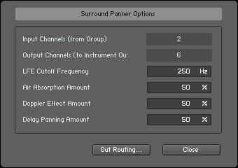
The Surround Panner Options dialog lets you adjust various parameters of the Doppler, Air Absorption, and Delay effects.
Options: This button will open a pop-up dialog which allows you to change the underlying parameters of the Doppler, Air Absorption, and Delay effects; furthermore, you can adjust the crossover frequency for the LFE channel. The dialog will also display the number of input and output channels that are currently in use. The button labeled Out Routing… will take you directly to the Channel Routing section of the Amplifier Module, where you can change channel routings and create mix-up or mix-down configurations to convert between channel layouts.
Surround Panner Automation
Automating the surround panner is particularly interesting for creating sounds that move around the room. There are several ways to accomplish this. If you need complete control over your motion patterns, you can use your host automation or external MIDI controllers to control the positioning parameters from outside Kontakt. If you want to create automatic motion, using Kontakt’s Modulation Router opens up a range of very interesting and creative possibilities.
Host/MIDI Automation
If you want to modulate the Surround Panner via your host or external MIDI controllers, you can assign external host automation data or MIDI controllers to the X Shift, Y Shift, Angle, and Distance parameters by dragging the respective automation sources from the Automation tab of the Side pane onto the knobs you’d like to automate. For more information about external automation, refer to section Automation Tab.
Internal Modulation
Using internal modulators on the Surround Panner offers a multitude of interesting possibilities, ranging from sounds that move around the room in a circular fashion to unpredictable and organic patterns of random motion. To create a modulation assignment, right-click a knob and choose a modulation source from the drop-down menu, then adjust the assignment parameters and the source’s controls (if any). Note that only the knobs to the right of the XY pad can be assigned for internal modulation. The knobs on the left can be automated via MIDI CC.
The buttons to the right of the XY pad can be assigned to a selected modulation source.
After you have created an assignment, observe the Surround Panner’s plane window when playing a note; you’ll notice that for every static source icon, there’s a darker icon moving along the plane. The bright icons display the sources’ original positions (which can still be changed by dragging the icons around), while the darker icons depict the actual positions after all modulations have been applied.
It’s hardly possible to describe the whole range of applications of modulating the Surround Panner’s parameters, so we’ll look at a few common scenarios instead. Re-creating these should get you a feel for what will be possible with some further experimentation.
Circular motion. In order to rotate your sources around a pivot point, thereby creating a circular motion path, modulate the Angle parameter of the Surround Panner via a Sawtooth LFO. The distance of each source from the pivot point can be changed either by dragging the original positions, or via adjusting the surround panner’s Distance parameter. To change the direction of the movement, enable the Invert button of the assignment in the Modulation Router. You can also synchronize the motion to the host or Master Editor tempo by switching the unit of the LFO’s Freq. parameter to a note value.
Random motion. This is a basic method to make your sources move around in an unpredictable way. Just assign two random modulators to the X Shift and Y Shift parameters. You can adjust how far the sources will stray from their original positions by adjusting the modulation intensities of these assignments.
Fly-by paths. Assigning envelope modulators to various parameters, most notably X Shift and Y Shift, allows you to define accurate and reproducible motion paths. It can get a while to understand how various envelope shapes relate to the resulting motion patterns, but once you’ve gotten the grip on it, you’ll be able to create virtually all kinds of pre-defined motion paths — especially when you’re using flexible envelopes.
Utilities
Utilities includes the Gainer, Inverter, Send Levels, Stereo Modeller and Surround Panner Insert effects. Utilities also includes the Group Insert effect the AET Filter and the Gainer Send effect.
AET Filter
This module constitutes the core of the powerful Authentic Expression Technology (AET) in Kontakt, which allows you to “morph” continuously between the timbral characteristics of multiple samples. The module is designed to work on the Group level, so it can only be placed in the Group Insert FX chain.
As the process of creating and using a morph extends to other elements of the user interface than this module itself, we’ll start with a high-level explanation of the idea and technology behind AET; if you’re just interested in a reference of the involved dialogs and the module’s controls, you can find those at the end of this section.
About Authentic Expression Technology
When sampling acoustic instruments, one of the common difficulties to overcome stems from the fact that most of them change their tonal characteristics radically throughout their range of dynamic and expression — a french horn played mf can sound very different from one played p. This makes it more difficult to capture the whole range of their sonic character in a convincing way with static samples alone. The traditional approach has been to tackle this problem with sheer size: Sample libraries that contain several dozen velocity layers per note have now become a common occurrence, and indeed, this is a good way to increase the sampled instrument’s level of detail. In a lot of cases, though, the shortcomings of turning highly dynamic instrumental sounds into static samples, such as noticeable timbre changes when moving from one velocity layer to the next, still persist.
With the Authentic Expression Technology (AET) in Kontakt, we’d like to introduce a radically different approach. The core of this technology is an FFT filter with a very high resolution, which is able to “imprint” frequency responses of almost any complexity on your signal. These frequency responses are derived from other samples in your patch via spectral analysis. For instance, the currently playing velocity layer could be filtered with the spectral information of the layer just above it to sonically shift it closer to the latter. By dynamically varying the amount of processing with the help of a modulation source (such as the velocity), you can thereby pass through any number of intermediate stages between two samples, thus “morphing” between them in real-time.
The process is not limited to dynamic layers, either: You can morph between different playing techniques of an instrument (such as a trumpet playing with and without mute) or even between different signals. This opens up a whole range of sound design possibilities — fancy a morph between a piano and a celesta!
The functionality of AET is split up into two logically separate parts. In the analysis phase, you tell Kontakt which Samples should be taken into consideration; it will then generate spectral “fingerprints” of these and save them for later use. This selection and setup process takes place in the Mapping Editor. Once the fingerprints have been created, they become available for selection within the AET Filter module, which you can insert into a Group Insert FX slot just like any other effect module. Here’s where the actual filtering takes place: With just a single parameter, you can control which of the stored frequency responses will be imparted to which amount on the currently playing sample.
Before we dive head-first into an actual use case of AET, we should explain two of the logical building blocks you’ll encounter in the setup process:
A Morph Layer is a group of non-overlapping Zones whose samples are directly related in some way; these are often stacks of velocity layers or multi-sampled Zones that cover a certain key range, or in other words, blocks of adjacent Zones in the Mapping Editor.
A Morph Map is a collection of one or more Morph Layers. This is what’s ultimately loaded into the AET Filter module, and its contents decide what the Morph knob on the module’s control panel will do. A Morph Map that contains only one Morph Layer is called a velocity map; in this case, the target frequency response will be derived from the Zone whose keyboard range matches the currently pressed key, and whose velocity range corresponds to the setting of the Morph knob. A Morph Map with multiple Morph Layers is the basis of an articulation morph; this is the more complex case, which allows you to set up morphs between two or more sets of Samples which are not necessarily related, such as different playing techniques or even entirely different instruments. Usually, the Morph Layers in such a map originate from different Groups in your Instrument.
In short: If you want to use the expression filter for dynamic velocity morphing, a Morph Map with only one Morph Layer will do fine (the Auto add AET velocity morph function described below will even set this up for you); if you want to do more complex things, you’ll have to create a Morph Map that consists of multiple, manually defined Morph Layers.
Now that you know what Authentic Expression Technology is and what it can do for you, let’s take a look at how to use it in real-world situations.
Creating a Velocity Morph
This is the basic use case, and since it is so common, Kontakt offers you a function that automates it for you. Just load or create an Instrument with multiple velocity layers, select all of your Zones in the Mapping Editor (take care that you don’t accidentally select multiple overlapping Zones; you might want to use the Selected Groups Only switch), then select the Auto add AET velocity morph command from the Edit menu.
You can find the “Auto add AET velocity morph” function both in the Edit menu and in the right-click context menu of the Mapping Editor.
When you open the Group Insert FX chain now, you’ll notice that Kontakt has added an AET Filter module for you. Take a look at its control panel and Modulation Router — it has already been set up with an auto-generated Morph Map, and the Morph knob is being modulated by the velocity.
The “Auto add AET velocity morph” function will add a ready-to-use AET Filter module to your Group Insert FX chain.
When you play some notes, Kontakt will still only play the Sample that’s assigned to the incoming velocity; the further the actual velocity is away from the middle velocity value of the played Zone, though, the more of the spectral characteristics of the Zone directly below or above will now be imparted on the sound. Once the velocity crosses the border to another Zone, the process will be reversed; now the next Zone will play, with the frequency response of the preceding one being used for filtering. This way, the timbral differences of your velocity layers are elegantly masked, resulting in a smooth dynamic response over the whole velocity range.
Tip
Of course, nothing stops you from assigning other modulation sources than the velocity to the Morph knob; you can just as well use a continuous MIDI controller or aftertouch for this purpose. Using a different modulation source for morphing makes it possible to sweep through the morph gradient while the sound is playing, which opens up very interesting performance possibilities. Keep in mind, though, that the filter will only act upon the Sample that was triggered when you pressed the key.
Creating an Articulation Morph
Setting up a simple velocity morph as described above is easy enough. There are times, though, when you need a more flexible way of configuring the morph filter. For example, you might want to set up a dynamically playable morph between two different, but musically related articulations of the same sound source, such as a choir singing “ahh” and “ooh”. This requires some more manual intervention. The procedure can be broken down into the following steps:
Create one Morph Layer for each of the Groups that the articulations are assigned to,
Combine two or more of these layers into a Morph Map, and
Load this map into an AET Filter module that you place in the Group Insert FX chain of the Group that should be processed.
In our example, we assume that the “ahh” and the “ooh” Zones are neatly split up into two different Groups, as would be the natural structure of a Kontakt patch. In a first step, select all Zones from the “ahh” Group (using the Selected Groups only function if needed), then choose Create AET morph layer from the Edit menu. A dialog window with a few options will appear.
Before creating a new Morph Layer from the selected Zones, Kontakt asks you to specify some details about the process.
Enter a descriptive name for your layer (such as “ahh”) and make sure that both the Tonal option is activated and the Smoothing parameter is set to its default value of 0.5, then click OK. Kontakt will now generate spectral fingerprints of all Zones and save them in a new Morph Layer. Once it has finished, repeat the process with the Zones in the other group. You have now created two new Morph Layers that contain spectral information which will be used in the resulting morph.
In order to tell Kontakt which morph layers you’d like to use in your morph, you’ll have to create a new Morph Map and add those layers to it.
To add a new Morph Map:
Open the AET Morph Map Editor from the Edit menu; a dialog window with an input line on top will appear.
Combine your Morph Layers into Morph Maps with the AET Morph Map Editor.
Enter a descriptive name here (such as “ahh -> ooh morph”) and click the Add: button. The Morph Layers you just prepared will now turn up in the right one of two lists at the bottom of the dialog, meaning that they’re available for inclusion in your new Morph Map. Select them one-by-one in the right list and move them into your map by clicking the left arrow button. Note that the order in which you include them is important; in our example, we want the filter to morph the original “ahh” samples into the frequency response of the “ooh” samples, so the “ahh” layer has to be on top of the list.
Before you finish, make sure you switch the Morph Map type to articulation morph instead of velocity morph; otherwise, Kontakt will display an error message, as velocity maps may only consist of a single Morph Layer. Click OK; your Morph Map is now ready for use.
Now would be a good time to stress the fact that in this scenario, the “ooh” samples will take no part whatsoever in the resulting sound; they just served as templates for setting up the morph filter. Even at the highest Morph setting, what you hear will actually be the “ahh” samples with the frequency response of the “ooh” samples superimposed. This also means that you should make sure that the “ooh” samples won’t be played when you press a key; the result would be a messy combination of filtered and unfiltered samples. The easiest way to do this is to turn the Volume knob of the “ooh” Group’s Amplifier Module all the way down.
To complete the process, switch over to the “ahh” Group, locate its Group Insert FX chain, and add an AET Filter module to an empty slot. Open the pull-down menu on the left side of its panel and select the Morph Map you just created. Now open the Modulation Router of the module and assign a controller, such as the modulation wheel, to the Morph parameter.
Setting the AET Filter module up in this way allows you to morph between your articulations in real-time using the modulation wheel.
That’s it — when you play some notes now, you can seamlessly morph between “ahh” and “ooh” using the modulation wheel. Of course, you can also create morphs across more than two Morph Layers; by repeating the steps above, you could easily add another layer of the choir singing “mmh” to your patch.
Now that you know how to use AET in your own Instruments, we’ll conclude this section with a description of the involved dialogs and their options.
Create AET Morph Layer Dialog
This dialog appears when you select the Create AET morph layer command from the Edit or context menu of the Mapping Editor.
Name: The name of this Morph Layer, which will be used to identify it in the Morph Map Editor.
Smoothing: This value affects how much the analyzed frequency response will be smoothed out before it’s being used as a template for the filter. Sensible values range from 0.1 (no smoothing) to around 2.0 (strong smoothing).
Tonal: When this option is active, Kontakt will analyze each sample harmonically in relation to the fundamental frequency of its respective root key value. You should only turn it off for material that’s entirely non-tonal, such as noise or percussion, or in case the root key value is wrong; in that case, Kontakt will perform a plain frequency analysis with no respect to harmonic structures.
Root Key Shift: As described above, Kontakt will use the root key value of a Zone to determine its Sample’s fundamental frequency when the Tonal option is activated. There are cases, though, where the root key value deliberately differs from the true fundamental frequency of the Sample. For instance, you could be working on a patch that places multiple playing techniques of the same instrument in different octaves, so that C2 and C4 play the same note, but with different articulations. In that case, using the root key value without correction would mislead the analyzer into considering the wrong frequencies; with the Root Key Shift parameter, you can specify an offset between the actual note of the Sample and its root key value in semitones. The default value of 0 assumes a correct root key setting; a value of -12 corresponds to the actual fundamental tone being one octave below the root key.
Analysis Range: Click and drag the borders of the selection range here to limit the analysis process to a certain time frame of each sample. When analyzing samples that change their timbre over time, this allows you to tell Kontakt at which point in a note the instrument will exhibit its most characteristic frequency spectrum, and exclude the rest from influencing the analysis result. For a piano or guitar, this would be the first seconds of each note; if you’d include the whole decay phase in the analysis, the average spectrum would turn out much darker.
Number of Zones: The number of Zones that are currently selected in the Mapping Editor and will be included in this Morph Layer when you click OK.
Morph Map Editor
This dialog appears when you select the Open AET morph map editor command from the Edit or context menu of the Mapping Editor.
Add: Enter a name in the input field next to this button and click it to create a new, empty Morph Map.
Map: This pull-down menu contains all available Morph Maps of your Instrument. Select one to edit it.
Remove: Deletes the currently selected Morph Map from the Instrument, thereby bypassing any AET Filter modules that reference this map.
Velocity/Articulation: Specify the principal type of the Morph Map here. Velocity maps morph between the Zones of a single Morph Layer, while Articulation Maps morph between multiple Morph Layers. Refer to the previous subsection for a thorough discussion of the differences.
Morph Layers in Current Map: Contains the names of all Morph Layers that make up the current map. Selecting a layer and clicking the right arrow button removes it from the map.
Available Morph Layers: Contains the names of the Morph Layers available for inclusion in the current map. Selecting a layer from this list and clicking the left arrow button will add this layer to the Morph Map.
Delete: Selecting a Morph Layer from one of the lists and clicking this button will remove it from your Instrument.
Rebuild: This will re-open the Create Morph Layer dialog for the currently selected Layer, which allows you to readjust its analysis parameters.
AET Filter Module Controls
This is the processing module that performs the actual filtering of the source material. When using AET via the Auto add AET velocity morph command, Kontakt will set this module up for you; in all other cases, you’ll have to insert it into a Group Insert FX chain yourself.
The control panel of the AET Filter module. Shown here is an auto-generated velocity morph across six layers.
Morph Map: Use this drop-down menu to load a Morph Map into the module.
Edit Morph Map: Click this button to open the Morph Map editor dialog explained in the previous section with the active Morph Map selected.
Morph: This is the most important parameter of the module; it should usually be modulated with an external source, such as the note velocity or a MIDI controller. Based on the contents of the selected Morph Map, Kontakt will build a continuous “morph gradient” that combines and connects the filter responses required to achieve the various timbres of the included Morph Layers with smooth transitions. Using the Morph parameter, you can set the filter to any point in this gradient. At its lowest value, the signal is changed towards the respective sample in the first Morph Layer of the map (if this happens to be identical with the playing sample, the filter will be flat); at its highest value, the sample is changed towards the respective sample in the last Morph Layer of the map. You can follow this behavior graphically in the morph curve view described below.
Amount: The amount to which the filter influences the resulting signal. At the lowest setting, the filter has no effect.
Filter Curve: This graph represents the actual, currently active filter response, which is the difference between the analyzed frequency response of the source (i.e. the currently playing Sample) and the target (i.e. the Morph Layer that appears in the Morph Map at the point that’s set with the Morph knob).
Morph Curve View: This is a graphical representation of the selected Morph Map and the resulting filter gradient. It’s divided into multiple color-coded sections and curves, with the sections depicting the Morph Layers that make up the map, and the curves representing the amount to which the frequency response of the respective layer will influence the final filter response at any point. On top of each section, the name of the respective Morph Layer is being shown for reference. At the peak of each curve, the currently played sample will be morphed into the frequency response of the respective layer to the maximum amount. The section and curve of the active sample (i.e. the source) are marked yellow; these correspond to a flat filter response. The sections and curves of the other layers are alternatingly colored white and blue. When playing a note and changing the Morph parameter, a horizontal, angled bracket below the graph marks the source and target points of the gradient that Kontakt uses to determine the final filter response.
Output: The output level of the module in dB.
Gainer
This module can be used both within the Instrument Insert Effects chain and as a send effect. Depending on where you choose to place it, it serves two different purposes. As an Instrument insert effect, you can boost or attenuate the signal level between the previous stage’s output and the next stage’s input. In other words, it works like an additional amplifier stage.
The idea behind using the Gainer as a send effect needs some more explanation. As every send effect can optionally route its own output signal to one of the Aux Channels in the Outputs section (instead of feeding it back into the Instrument), the Gainer can act as a transparent bridge between the send slots and the Aux Channels. Therefore, it allows you to send signals at adjustable levels to the Aux Channels on a per-Group basis, which greatly increases routing flexibility and can even save a lot of CPU resources — just move effects that you would otherwise have created as send effects in multiple Instruments to an Aux Channel instead, and use the Gainer within the Instruments’ send effects slots in order to forward signals to this Aux channel. By changing the Aux channel’s physical output assignment, you can even use external effects, whether they are plug-ins in your host program or outboard devices, from within Groups.
After you have inserted the Gainer module into a send slot, you’ll notice that in addition to the Gain control, it also provides the Return control which is common to all send effects on the right side of its panel. Next to the numerical readout of this control, you’ll notice a small „I“ icon. Clicking on it opens a drop-down menu that allows you to select one of the Aux Channels as the routing target for the module’s output. This way, whatever you’ll send to this slot via the Send Levels module will end up on the specified Aux Channel.
Gainer contains the following control:

Gain: The amplification or attenuation factor that will be applied to the signal in dB.
Inverter
With this module, you can invert the phase of your audio signal, or swap the left and right channels. Since the Inverter only makes sense as an insert effect, you can use this module only in the Group Insert Effects and Instrument Insert Effects chains.
Inverter contains the following controls:

PhaseInvert: Inverts the signal phase polarity.
Pan L <> R: Swaps the stereo channels.
Send Levels
This utility module can be added to the Group Insert Effects and Instrument Insert Effects chains and allows you to send a signal from within the insert chain to any existing send effect at adjustable levels.
This module contains the following controls:

Levels: On the left side of the Send Levels module, you’ll see a level control for each send effect that’s currently in one of your Instrument Send Effects slots — if you didn’t add any send effects yet, the panel will be empty. The knobs allow you to adjust the level at which the signal will be sent to the respective effect.
Level meters: These LED-style peak meters provide visual feedback on the send levels.