Effect reference
This section describes the functionality of all of Maschine's internal effects, organized in various categories.
Maschine provides a healthy selection of more than 20 different Effect Plug-ins that can be quickly applied to Sounds, Groups and the Master, all as insert effects. By using Maschine’s powerful routing system, it is also easy to setup send effects, build complex effect chains or apply an effect to an external source that is connected to your audio interface, such as an instrument, vocals or a turntable. We recommend you load a Project from the factory library to get to know how effects can be used.
This chapter will describe the effects and their parameters. For more information on how to use effects within your Project, refer to Using effects.
Available effects
Many types of effects are available and nearly all applications are represented. You will, of course, find traditional effects such as delays, reverbs and distortions, as well as engineering tools such as EQs, dynamics, and filters. But we have also provided you with a series of unique and unusual effects such as Reflex, Ice, and Resochord.
Effects are organized into the following categories:
Dynamics: Compressor, Gate, Transient Master, Limiter, and Maximizer. Refer to Dynamics.
Filtering effects: EQ, Filter, and Cabinet. Refer to Filtering effects.
Modulation effects: Chorus, Flanger, FM, Freq Shifter, and Phaser. Refer to Modulation effects.
Spatial and Reverb effects: Ice, Metaverb, Reflex, Reverb, and Plate Reverb. Refer to Spatial and reverb effects.
Delays: Beat Delay, Grain Delay, Grain Stretch, and Resochord. Refer to Delays.
Distortion effects: Distortion, Lofi, and Saturation. Refer to Distortion effects.
Perform FX: Designed for spontaneous, tactile control in recording or live performance, these complex multi-effects alter motion, space, dynamics, and more for added expression. Refer to Perform FX.
Dynamics
Compressor
This is a classic compression effect to control the dynamic information of an audio signal. You can use the Compressor to fatten up your drums or to control signals that have a very wide dynamic range.
In addition to the legacy Classic mode, the Compressor provides an alternate Feedback mode. If this effect is used in a Sound or a Group, it also provides a Side-Chain Input page (in the Control area and on your controller).
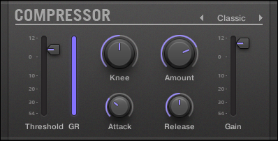
The Compressor panel in the Plug-in Strip.
Main page
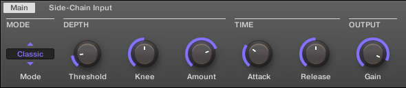
The Compressor in the Control area: Main page.
Parameter | Description |
|---|---|
MODE Section | |
Mode | Selects between two operation modes: Classic (default setting) and Feedback. Whereas Classic mode generates a cleaner and more precise compression, Feedback mode introduces a subtle change in transient shape and frequency responsiveness. The memory-based envelope detection along with the knee-dependent ratio and gain give this mode a typical vintage feel. |
DEPTH Section | |
Threshold | This value determines the threshold at which the Compressor starts to work. |
Knee | This parameter defines how the Compressor starts to work: with a low setting, the transition into compression is soft, whereas with a high setting, the Compressor abruptly starts to work once the threshold is reached. |
Amount | The amount of compression effect, often called ratio in typical applications. |
TIME Section | |
Attack | Use Attack to adjust how fast the Compressor reacts on the incoming signal: the more you dial it to the right, the slower it will react. Longer Attack times let more transients through. |
Release | The time the compressor will take to stop compressing after the input signal falls below the threshold. With longer release times it takes more time to get back to normal. |
OUTPUT Section | |
Gain | Use Gain to adjust the volume of the resulting signal; sometimes called “make-up gain” as it can be used to compensate for any reduction in the signal induced by the settings above. |
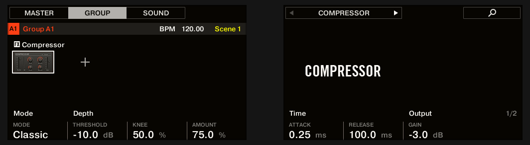
The Compressor on the controller: MAIN page.
Side-Chain Input page
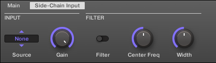
The Compressor in the Control area: Side-Chain Input page.
Parameter | Description |
|---|---|
INPUT Section | |
Source | Selects the audio signal you want to use as side-chain signal to control the Plug-in. Available options are None (side-chain deactivated, default setting), the outputs of all (other) Sounds , and the outputs of all (other) Groups. In the menu these outputs are labeled as follows: For Groups: [Group name] (e.g., Drums) For Sounds: [Group name]: [Sound name] (e.g., Drums: Kick) In the selector display these outputs are labeled as follows: For Groups: [Group name] (e.g., Drums) For Sounds: [Group letter+number]:S[Sound number] (e.g., A1:S4 for the Sound 4 of Group A1) |
Gain | Adjusts the input level of the side-chain signal fed into the Plug-in. |
FILTER Section | |
Filter | Activates a filter on the side-chain input. This filter can be useful to select only a specific frequency range of the side-chain signal to control the Plug-in. |
Center Freq | Adjusts the center frequency of the filter. |
Width | Adjusts the bandwidth of the filter. |
Notice
On your controller the outputs available in the SOURCE parameter are labeled as in the display of the Source selector described above.
Notice
For more information on how to use the side-chain input, please refer to section Using the side-chain input.
Level meters in the Compressor panel (Plug-in Strip)
In the Plug-in Strip, the Compressor panel offers a few extra features not available in the Control area:
The Threshold and Gain faders (corresponding to the Threshold and Gain parameters of the Main page in the Control area) provide level meters for visual monitoring of the input and output levels. In particular, by comparing the input level with the position of the Threshold fader, you can easily see you which parts of the signal will be compressed, and adjust the Threshold fader accordingly.
An additional GR level meter indicates the gain reduction currently applied by the Compressor to the input signal.
Gate
The Gate cuts any part of the input signal which falls below the input threshold. This can be used to rhythmically chop the signal and make it stutter or sound staccato.
If this effect is used in a Sound or a Group, it also provides a Side-Chain Input page (in the Control area and on your controller).
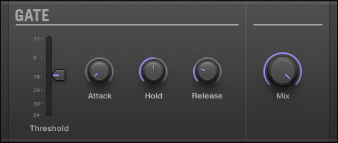
The Gate panel in the Plug-in Strip.
Main page
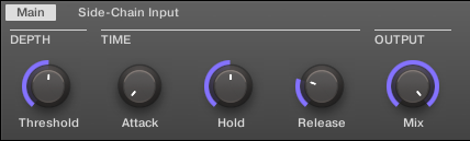
The Gate in the Control area: Main page.
Parameter | Description |
|---|---|
DEPTH Section | |
Threshold | This value determines the threshold at which the Gate starts to work. Higher values will let only the loudest parts of the signal through the Gate. |
TIME Section | |
Attack | Use Attack to adjust how fast the Gate reacts to the incoming signal: the more you dial it to the right, the slower it will react, resulting in a softer transition between the gated and the not gated parts of the signal. |
Hold | The Hold parameter is used to determine how long the gated signal is held; lower values will result in a more "choppy" effect. |
Release | The time the Gate will take to release the input signal after it rises above the threshold. |
OUTPUT Section | |
Mix | Mix lets you adjust the amount of the effect in relation to the dry original audio signal. |
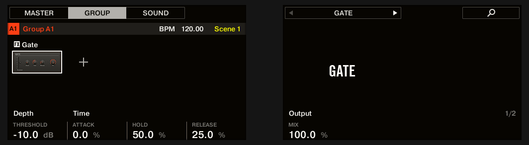
The Gate on the controller: MAIN page.
Side-Chain Input page

The Gate in the Control area: Side-Chain Input page.
Parameter | Description |
|---|---|
INPUT Section | |
Source | Selects the audio signal you want to use as side-chain signal to control the Plug-in. Available options are None (side-chain deactivated, default setting), the outputs of all (other) Sounds , and the outputs of all (other) Groups. In the menu these outputs are labeled as follows: For Groups: [Group name] (e.g., Drums) For Sounds: [Group name]: [Sound name] (e.g., Drums: Kick) In the selector display these outputs are labeled as follows: For Groups: [Group name] (e.g., Drums) For Sounds: [Group letter+number]:S[Sound number] (e.g., A1:S4 for the Sound 4 of Group A1) |
Gain | Adjusts the input level of the side-chain signal fed into the Plug-in. |
FILTER Section | |
Filter | Activates a filter on the side-chain input. This filter can be useful to select only a specific frequency range of the side-chain signal to control the Plug-in. |
Center Freq | Adjusts the center frequency of the filter. |
Width | Adjusts the bandwidth of the filter. |
Notice
On your controller the outputs available in the SOURCE parameter are labeled as in the display of the Source selector described above.
Notice
For more information on how to use the side-chain input, please refer to section Using the side-chain input.
Input level meter in the Gate panel (Plug-in Strip)
In the Plug-in Strip, the Gate panel offers an extra feature not available in the Control area: The Threshold fader (corresponding to the Threshold parameter of the Main page in the Control area) provides a level meter for visual monitoring of the input level. By comparing this input level with the position of the Threshold fader, you can easily see you which parts of the signal will pass through the Gate.
Transient Master
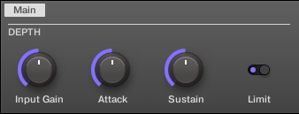
The Transient Master allows you to emphasize or attenuate the transients of your audio material by modifying the envelopes of every attack and sustain phase. For example, by increasing the attacks of a snare or a kick, you can build powerful percussive sounds without running the risk of damaging their natural sounding. Unlike other dynamic effects (compressors, limiters, etc.), the Transient Master does not use the input signal level to decide when to come into effect (no threshold) but rather affects all parts of the signal. This retains the musical character of your sound while keeping operation simple and intuitive: Adjust the desired amount of accentuation for the attack and/or sustain phases and you’re all set!
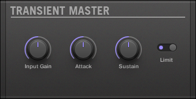
The Transient Master panel in the Plug-in Strip.
The Transient Master in the Control area.
Parameter | Description |
|---|---|
DEPTH Section | |
Input Gain | Adjusts the level of the input signal. This allows you to offset the overall level once you have set the desired effect, in order to counterbalance the gain or loss of level that might occur. |
Attack | Sharpens/softens the attack phases in your signal. With the knob at the middle position, the attack phases are not altered. From this position, turning the Attack knob to the left softens the attack phases, while turning it to the right sharpens them. |
Sustain | Prolongs/shortens the sustain phases in your signal. With the knob at the middle position, the sustain phases are not altered. From this position, turning the Sustain knob to the left shortens the sustain phases, while turning it to the right prolongs them. |
Limit | Activates a hard limiter at the output, preventing the output signal from clipping. This can be useful when the Attack knob is set to a high value as this may produce amplified attack phases which become too loud. |
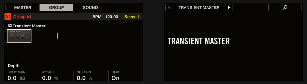
The Transient Master on the controller.
Limiter
The Limiter does two things: firstly it ensures that the signal level stays below 0 dB, thus preventing digital clipping. But it can also increase the overall perceived volume by reducing the threshold. It is recommended to place the Limiter in a Master Plug-in slot. However, please note that the Limiter introduces a small latency.
If this effect is used in a Sound or a Group, it also provides a Side-Chain Input page (in the Control area and on your controller).
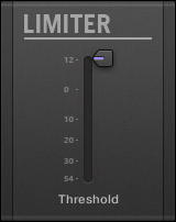
The Limiter panel in the Plug-in Strip.
Main Page
The Limiter in the Control area: Main page.
Element | Description |
|---|---|
MODE Section | |
Mode | Selects from two different limiter types. The available modes are Legacy and Transparent. |
DEPTH Section (Transparent mode only) | |
Threshold | This value determines the threshold where the Limiter kicks in. If you use it to prevent your signal from clipping, leave it at 0 dB; if you want to make your signal louder, dial the Knob to the left. Available values range in decibels from -40.0 dB to 0.0 dB (default: 0.0 dB). |
Release | The time the limiter will take to stop limiting after the input signal falls below the threshold. With longer release times it takes more time to get back to normal. Available values can be adjusted in milliseconds from 1.0ms to 500.0ms (default: 1.0ms). |
OUTPUT Section | |
Ceiling | Adjusts the maximum output level, or ceiling. The signal will not rise above this. Available values range in decibels from -40.0 dB to -0.3 dB (default: -0.3 dB). |

The Limiter on the controller: MAIN page.
Side-Chain Input page
The Limiter in the Control area: Side-Chain Input page.
The Modulation page contains one parameter: Velocity.
Element | Description |
|---|---|
INPUT Section | |
Source | Selects the audio signal you want to use as side-chain signal to control the Plug-in. Available options are None (side-chain deactivated, default setting), the outputs of all (other) Sounds, and the outputs of all (other) Groups. In the menu these outputs are labeled as follows:
|
Gain | Adjusts the input level of the side-chain signal fed into the Plug-in. Available values range from 0.00 dB to 1.00 (default: 1.00). |
FILTER Section | |
Filter | Activates a filter on the side-chain input. This filter can be useful to select only a specific frequency range of the side-chain signal to control the Plug-in. Available values are off and on (default: off). |
Center Freq | Adjusts the center frequency of the filter. Available values range in kilohertz from 20.0 Hz to 20.0 kHz (default: 632.5 kHz). |
Width | Adjusts the bandwidth of the filter. Available values range from 0 to 100 %. |
Notice
On your controller the outputs available in the SOURCE parameter are labeled as in the display of the Source selector described above.
Notice
For more information on how to use the side-chain input, please refer to section Using the side-chain input.
Input level meter in the Limiter panel (Plug-in Strip)
In the Plug-in Strip, the Limiter panel offers an extra feature not available in the Control area: The Threshold fader (corresponding to the Threshold parameter of the Main page in the Control area) provides a level meter for visual monitoring of the input level. By comparing this input level with the position of the Threshold fader, you can easily see which parts of the signal will be limited, and adjust the Threshold fader accordingly.
Maximizer
The Maximizer reduces the dynamics within the sound, making the overall sound louder. It is similar to the Limiter, but it is specifically designed for increasing the perceived volume.
If this effect is used in a Sound or a Group, it also provides a Side-Chain Input page (in the Control area and on your controller).
The Maximizer panel in the Plug-in Strip.
Main page
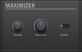
The Maximizer in the Control area: Main page.
Parameter | Description |
|---|---|
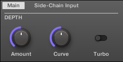
DEPTH Section | |
Amount | This parameter is used to adjust the amount of the Maximizer effect. Turn the knob clockwise to increase the loudness of the signal. |
Curve | Controls the compression knee; higher values tend to result in faster and more aggressive gain control. |
Turbo | Turbo intensifies the effect the Maximizer has on the signal by causing the maximizing algorithm to be applied twice. |
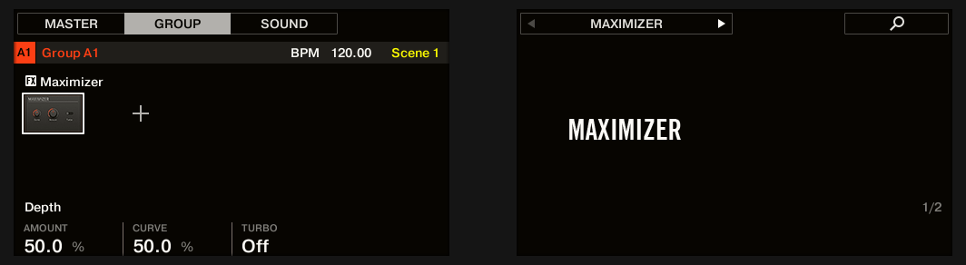
The Maximizer on the controller: MAIN page.
Side-Chain Input page

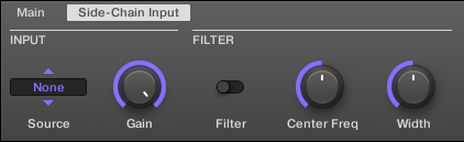
The Maximizer in the Control area: Side-Chain Input page.
Parameter | Description |
|---|---|
INPUT Section | |
Source | Selects the audio signal you want to use as side-chain signal to control the Plug-in. Available options are None (side-chain deactivated, default setting), the outputs of all (other) Sounds , and the outputs of all (other) Groups. In the menu these outputs are labeled as follows: For Groups: [Group name] (e.g., Drums) For Sounds: [Group name]: [Sound name] (e.g., Drums: Kick) In the selector display these outputs are labeled as follows: For Groups: [Group name] (e.g., Drums) For Sounds: [Group letter+number]:S[Sound number] (e.g., A1:S4 for the Sound 4 of Group A1) |
Gain | Adjusts the input level of the side-chain signal fed into the Plug-in. |
FILTER Section | |
Filter | Activates a filter on the side-chain input. This filter can be useful to select only a specific frequency range of the side-chain signal to control the Plug-in. |
Center Freq | Adjusts the center frequency of the filter. |
Width | Adjusts the bandwidth of the filter. |
Notice
On your controller the outputs available in the SOURCE parameter are labeled as in the display of the Source selector described above.
Notice
For more information on how to use the side-chain input, please refer to section Using the side-chain input.
Filtering effects
EQ
Use the EQ to boost or cut selective frequencies of the audio signal. The EQ is mainly a tool to tailor your audio signal to taste by cutting out selected frequencies or boosting others, but can also be used as a DJ-style cut-and-boost effect. Please note that in the Control area and on your controller the EQ parameters are spread over two pages.
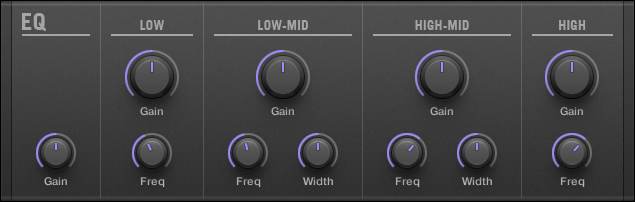
The EQ panel in the Plug-in Strip.
Freq / Gain page
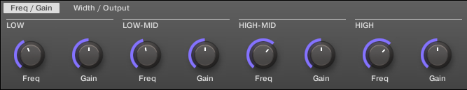
The EQ in the Control area: Freq / Gain page.
Parameter | Description |
|---|---|
LOW Section | |
Freq | Frequency selector for the low frequency band. Ranges from 20 Hz to 8 kHz. |
Gain | This determines how much the selected frequency is increased/attenuated by. |
LOW-MID Section | |
Freq | Frequency selector for the first mid-frequency band. Ranges from 40 Hz to 16 kHz. |
Gain | This determines how much the selected frequency is increased/attenuated by. |
HIGH-MID Section | |
Freq | Frequency selector for the second mid-frequency band. Ranges from 40 Hz to 16 kHz. |
Gain | This determines how much the selected frequency is increased/attenuated by. |
HIGH Section | |
Freq | Frequency selector for the high frequency band. Ranges from 50 Hz to 20 kHz. |
Gain | This determines how much the selected frequency is increased/attenuated by. |
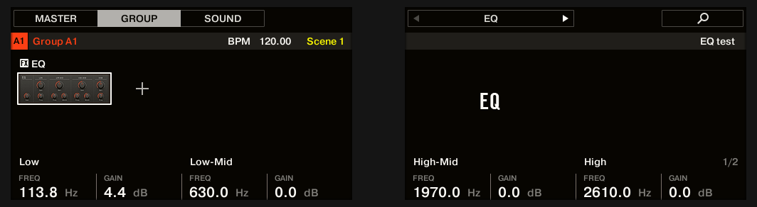
The EQ on the controller: FREQ / GAIN page.
Width / Output page
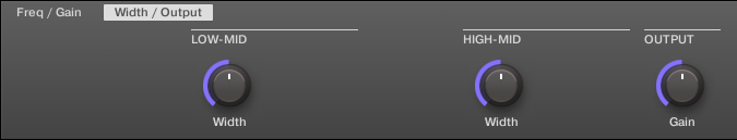
The EQ in the Control area: Width / Output page.
Parameter | Description |
|---|---|
LOW-MID Section | |
Width | Bandwidth control for the first mid-frequency band. |
HIGH-MID Section | |
Width | Bandwidth control for the second mid-frequency band. |
OUTPUT Section | |
Gain | Gain control for the EQ altogether. |
Filter
Filter with selectable characteristics that can be modulated via LFO or envelope. There are many applications for a filter: it can be used to emulate a synthesizer more realistically or to filter out selected frequencies and create filter-sweeps.
If this effect is used in a Sound or a Group, it provides a Side-Chain Input page (in the Control area and on your controller).
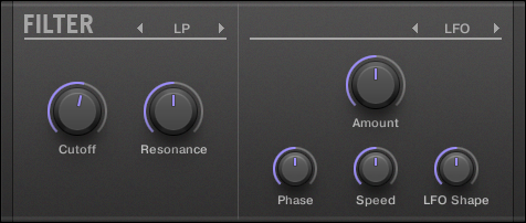
The Filter panel in the Plug-in Strip.
Main page
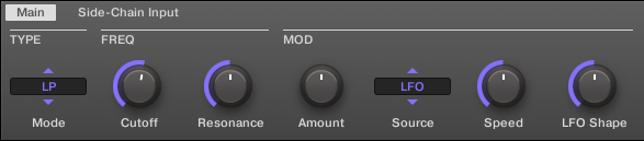
The Filter in the Control area: Main page.
Parameter | Description |
|---|---|
TYPE Section | |
Mode | Select between four different filter modes: LP (low-pass), BP (band-pass), HP (high-pass), and Notch. Depending on the mode selected, the following parameters vary as indicated. |
FREQ Section | |
Cutoff | Controls the cutoff frequency of the filter. |
Resonance | Controls the amount of resonance, i.e. the amount of amplification near the cutoff frequency. It is not available with filter mode Notch. |
MOD Section | |
Amount | Defines how much the Filter gets modulated by the modulation source. |
Source | Select between three different modulation sources: LFO, LFO Sync, and Envelope. Depending on your choice for the modulation source, the following parameters appear to the right: |
Source: LFO | Articulates the opening and closing of the filter using an LFO. Use this setting in combination with Speed, and LFO Shape. |
Speed | Defines the speed of the modulation in hertz ranging from 0.03 Hz up to 16 Hz. |
LFO Shape | Defines how the LFO evolves over time. |
Source: LFO Sync | Articulates the opening and closing of the filter using an LFO in sync to the tempo of the Project. Use this setting in combination with Speed, LFO Shape, and Phase. |
Speed | Defines the speed of the modulation in note values from 16/1 (one cycle every 16 bars) up to 1/32 note. |
LFO Shape | Defines how the LFO evolves over time. |
Phase | Adjusts the start phase of the LFO. |
Source: Envelope | Articulates the opening and closing of the filter using an envelope. Use this setting in combination with Decay, Smooth, and Shape. |
Decay | Adjusts how fast the envelope fades out. |
Smooth | Smooths the shape of the envelope. |
Shape | Changes the shape of the envelope. |
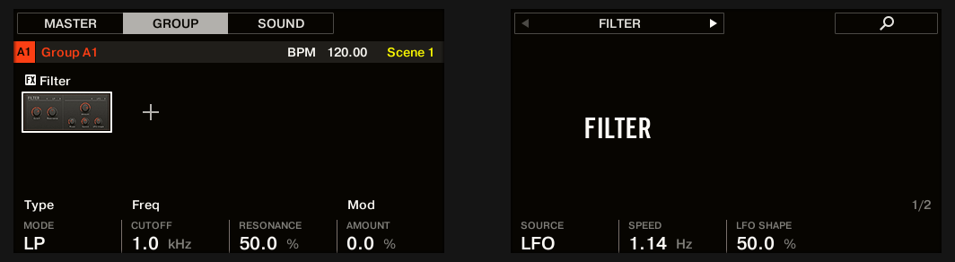
The Filter on the controller: MAIN page.
Side-Chain Input page

The Filter in the Control area: Side-Chain Input page.
Parameter | Description |
|---|---|
INPUT Section | |
Source | Selects the audio signal you want to use as side-chain signal to control the Plug-in. Available options are None (side-chain deactivated, default setting), the outputs of all (other) Sounds , and the outputs of all (other) Groups. In the menu these outputs are labeled as follows: For Groups: [Group name] (e.g., Drums) For Sounds: [Group name]: [Sound name] (e.g., Drums: Kick) In the selector display these outputs are labeled as follows: For Groups: [Group name] (e.g., Drums) For Sounds: [Group letter+number]:S[Sound number] (e.g., A1:S4 for the Sound 4 of Group A1) |
Gain | Adjusts the input level of the side-chain signal fed into the Plug-in. |
FILTER Section | |
Filter | Activates a filter on the side-chain input. This filter can be useful to select only a specific frequency range of the side-chain signal to control the Plug-in. |
Center Freq | Adjusts the center frequency of the filter. |
Width | Adjusts the bandwidth of the filter. |
Notice
On your controller the outputs available in the SOURCE parameter are labeled as in the display of the Source selector described above.
Notice
For more information on how to use the side-chain input, please refer to section Using the side-chain input.
Cabinet
The Cabinet Emulation is a cabinet and microphone component that proves full control over all the (post-amp) stages of recording a guitar tone. Cabinet Emulation includes the four cabinet types, and the variable positioning of six different microphones.

The Cabinet Emulation effect in the Plug-in Strip.
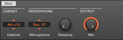
The Cabinet Emulation in the Control area (Main page depicted).
Main page
Element | Description |
|---|---|
CABINET Section | |
Cabinet | Selects from four different cabinet types, which includes:
|
MICROPHONE Section | |
Microphone | Selects from six different microphone types, which includes:
|
Distance | Adjusts the distance of the microphone from the cabinet. Available values range from 0.0 to 100.0% (default: 0.0%). |
OUTPUT Section | |
Mix | Adjusts the ratio between the effect (wet) signal and original (dry) signals. Available values range from 0.0 to 100.0% (default: 100.0%). |
Modulation effects
Chorus
The Chorus is useful to “thicken” signals and enhance or add stereo content. It is most effective on melodic sounds, but can also be used on hi-hats to make them more vivid or on a voice sample to create a doubling effect (thereby making it sound as if there were several voices). It works by splitting the audio signal up into two versions and slightly detuning one of them.
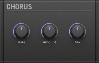
The Chorus panel in the Plug-in Strip.
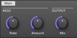
The Chorus in the Control area.
Parameter | Description |
|---|---|
MOD Section | |
Rate | The Rate knob defines how fast the phase (and thus the perceived pitch) of the detuned signal is being modulated. |
Amount | The amount of the Chorus effect. |
OUTPUT Section | |
Mix | Mix lets you adjust the amount of the effect in relation to the dry original audio signal. |
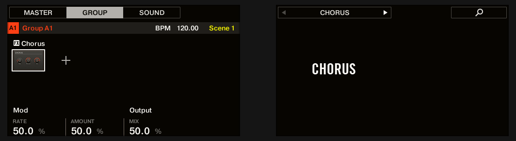
The Chorus on the controller.
Flanger
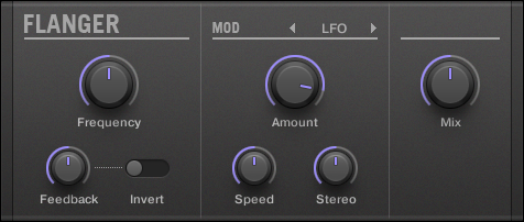
Classic flanger effect with LFO and envelope modulation. The Flanger sounds a bit like the Chorus, but the difference between them is that the Flanger modulates the signal faster, it is equipped with a feedback mechanism, and can be synchronized to the tempo of the Project.
The Flanger panel in the Plug-in Strip.
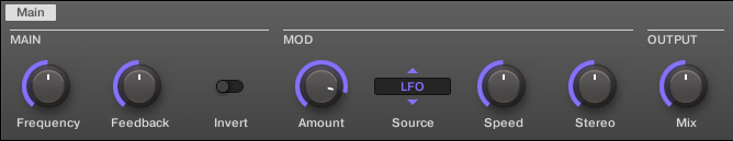
The Flanger in the Control area.
Parameter | Description |
|---|---|
MAIN Section | |
Frequency | This defines the center frequency of the Flanger. |
Feedback | Adjusts the amount of output signal fed back into the input. |
Invert | Inverts the Flanger. |
MOD Section | |
Amount | This defines how much the Flanger gets modulated by the modulation source. |
Source | Here you can select the modulation source of the Flanger: available options are LFO, LFO Sync, and Envelope. Depending on your selection, the parameter to the right will change. |
Speed (LFO) | Defines the speed of the LFO in a range from 0.03 Hz up to 8 Hz. |
Speed (LFO Sync) | Defines the speed of the LFO in note values from 16/1 (one cycle every 16 bars) up to 1/16 note. |
Shape (Envelope) | Change the shape of the envelope here. |
Stereo | This parameter widens the stereo field of the effect. |
OUTPUT Section | |
Mix | Mix lets you adjust the amount of the effect in relation to the dry original audio signal. |

The Flanger on the controller.
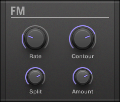
FM
FM modulates the frequency of the audio signal based on FM synthesis. High frequency settings are useful for adding a subtle “gritty” texture to the input signal.
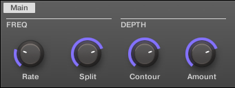
The FM panel in the Plug-in Strip.
FM in the Control area.
Parameter | Description |
|---|---|
FREQ Section | |
Rate | This is for adjusting the speed of the FM modulation. |
Split | The Split control determines the extent to which the FM effect is applied to high frequencies via a crossover. Turn to the right to affect higher frequencies. It can be useful to eliminate noise artifacts caused by FM of very high signals. With high Split settings, the effect becomes more “gritty” and crackling. |
DEPTH Section | |
Contour | Contour determines the extent to which the input volume affects the intensity of the effect. |
Amount | Determines the amount of the FM effect. |
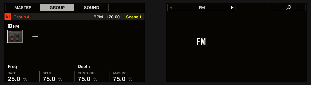
The FM on the controller.
Freq Shifter
The Freq Shifter shifts selected frequencies of the audio signal by a user-specified amount. With high frequencies it sounds like a pitch shifter; with low frequencies it sounds like a special chorus.
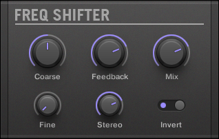
The Freq Shifter panel in the Plug-in Strip.
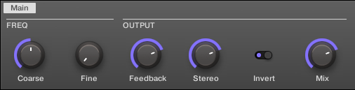
The Freq Shifter in the Control area.
Parameter | Description |
|---|---|
FREQ Section | |
Coarse | This is used to define the basic frequency of the Freq Shifter. |
Fine | Fine-tune the frequency here. |
OUTPUT Section | |
Feedback | Adjusts the amount of output signal fed back into the input. Increasing this parameter will increase the intensity of the effect. |
Stereo | This parameter widens the stereo field of the effect. |
Invert | Inverts the settings of the Freq Shifter. |
Mix | Mix lets you adjust the amount of the effect in relation to the dry original audio signal. |
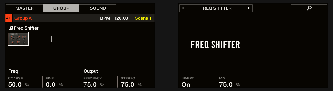
The Freq Shifter on the controller.
Phaser
Classic phaser with LFO and envelope modulation.
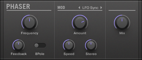
The Phaser panel in the Plug-in Strip.
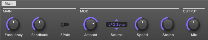
The Phaser in the Control area.
Parameter | Description |
|---|---|
MAIN Section | |
Frequency | This defines the center frequency of the Phaser. |
Feedback | Adjusts the amount of output signal fed back into the input. |
8Pole | Activating this causes the Phaser to use the 8Pole mode, resulting in a more intense phasing effect. |
MOD Section | |
Amount | This defines how much the Phaser gets modulated by the modulation source. |
Source | Here you can select the modulation source of the Phaser: available options are LFO, LFO Sync, and Envelope. Depending on your selection, the parameter to the right will change. |
Speed (LFO) | Defines the speed of the LFO in a range from 0.03 Hz up to 8 Hz. |
Speed (LFO Sync) | Defines the speed of the LFO in note values from 16/1 (one cycle every 16 bars) up to 1/16 note. |
Shape (Envelope) | Change the shape of the envelope here. |
Stereo | This parameter widens the stereo field of the effect. |
OUTPUT Section | |
Mix | Mix lets you adjust the amount of the effect in relation to the dry original audio signal. |
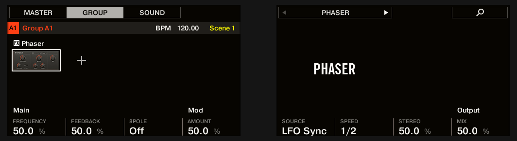
The Phaser on the controller.
Spatial and reverb effects
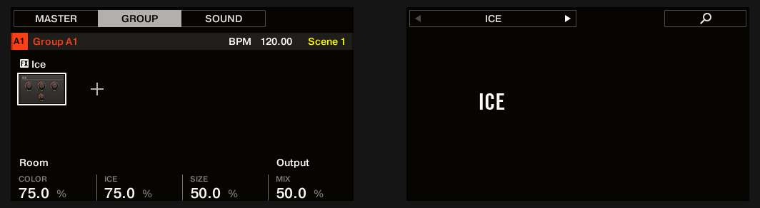
Ice
This is a special reverb for getting cold and metallic sound. Ice includes a bank of self-oscillating filters for interesting and colorful effects. In the Project “Come Into My Disco” from the Maschine factory library, you can hear how it creates deep soundscapes during the break in Scene 6.
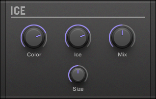
The Ice panel in the Plug-in Strip.
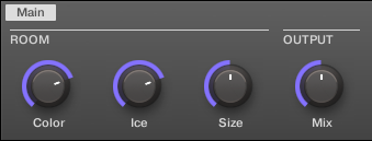
The Ice in the Control area.
Parameter | Description |
|---|---|
ROOM Section | |
Color | With lower settings, the general sound is a bit more muffled. The higher the Color value, the brighter it sounds. |
Ice | The “ICE” factor: higher values sound more metallic. |
Size | Adjust the size of the virtual room here. |
OUTPUT Section | |
Mix | Mix lets you adjust the amount of the effect in relation to the dry original audio signal. |
The Ice on the controller.
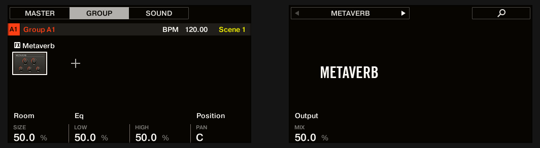
Metaverb
Like the Reverb, the Metaverb adds spatial room information. However, in contrast to the Reverb it has a much more “synthetic” sound, which is particularly suited for melodic content.
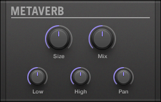
The Metaverb panel in the Plug-in Strip.
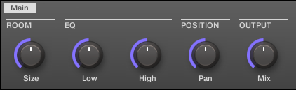
The Metaverb in the Control area.
Parameter | Description |
|---|---|
ROOM Section | |
Size | Adjust the size of the virtual room here. |
EQ Section | |
Low | Low band EQ to cut or boost bass frequencies. |
High | High band EQ to cut or boost high frequencies. |
POSITION Section | |
Pan | This pans the dry signal. This is useful because the dry signal can not be panned after the effect without panning the reverb itself, which is unnatural. |
OUTPUT Section | |
Mix | Mix lets you adjust the amount of the effect in relation to the dry original audio signal. |
The Metaverb on the controller.
Reflex
This is a special resonating reverb. At moderate settings the Reflex can be useful to emulate small, “tight” rooms. At more extreme settings, it can produce interesting artificial, metallic textures.
Tip
Automating the Color parameter usually yields very pleasing results.
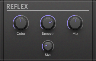
The Reflex panel in the Plug-in Strip.
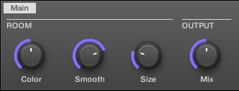
The Reflex in the Control area.
Parameter | Description |
|---|---|
ROOM Section | |
Color | At lower settings, the general sound is a bit more muffled; the higher the settings, the brighter it sounds. |
Smooth | With this parameter, you can soften the metallic character of Reflex. |
Size | Adjust the size of the virtual room here. |
OUTPUT Section | |
Mix | Mix lets you adjust the amount of the effect in relation to the dry original audio signal. |
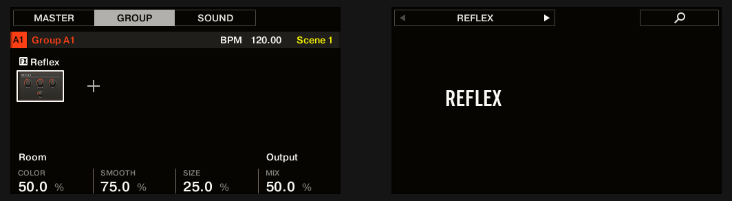
The Reflex reverb on the controller.
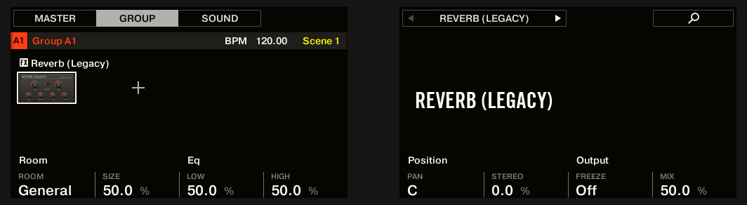
Reverb (Legacy)
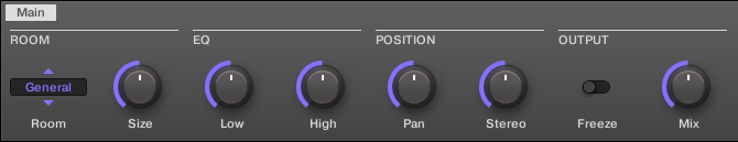
This reverb is best for most common applications. The Reverb adds room information to the signal, making it sound more spacious and natural. It is particularly suited to drum sounds, but also useful to add a more “natural” sound for all sorts of other signals.
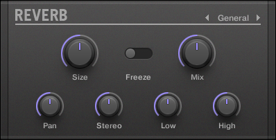
The Reverb panel in the Plug-in Strip.
The Reverb in the Control area.
Parameter | Description |
|---|---|
ROOM Section | |
Room | This allows you to choose one of four basic characteristics of the Reverb: General, Bright, Guitar, and Shatter. |
Size | Adjust the size of the virtual room here. |
EQ Section | |
Low | Low band EQ to cut or boost bass frequencies. |
High | High band EQ to cut or boost high frequencies. |
POSITION Section | |
Pan | This pans the dry signal. This is useful because the dry signal can not be panned after the effect without panning the reverb itself, which is unnatural. |
Stereo | This parameter widens the stereo field of the effect. |
OUTPUT Section | |
Freeze | Enabling Freeze both mutes the dry signal and traps the current state of the Reverb output in a temporary buffer to make it last much longer. This is a powerful tool for playing live: By simultaneously tweaking the Mix knob nearby, you can create striking breaks! Setting the EQ’s Low and High controls to generous values will further increase the effect. |
Mix | Mix lets you adjust the amount of the effect in relation to the dry original audio signal. |
The Reverb on the controller.
Reverb
The Reverb effect provides three different modes which are described in this section.
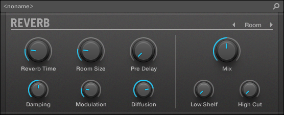
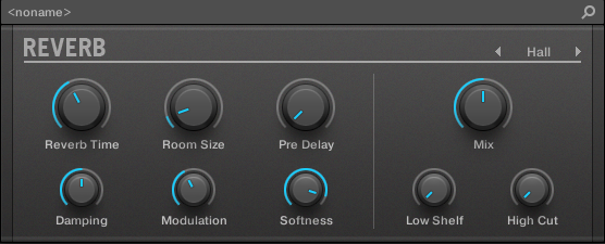
The Room Reverb panel in the Plug-in Strip.
Reverb Room
The Room mode is suited to drum and percussive sounds, and particularly sounds good when used on snares. Modulate the Room Size, and Pre Delay parameters to create special effects.

The Reverb effect in the Plug-in Strip.
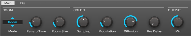
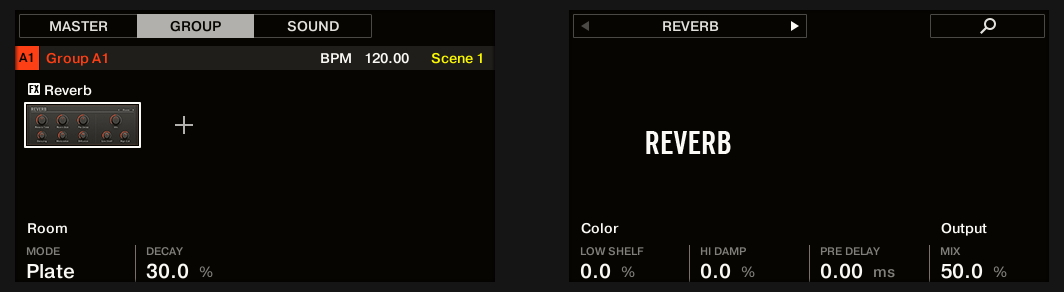
The Reverb in the Control area (Main page depicted).
Main page
Element | Description |
|---|---|
ROOM Section | |
Mode | Allows you to choose one of three basic modes of Reverb: Room, Hall, and Plate (default: Room). |
Reverb Time | Adjusts the reverb decay time. Turn clockwise to increase decay. Available values range can be adjusted in seconds from 0.5s to 20.2s (default: 1.0s). |
Reverb Size | Adjust the size of the simulated room. Turn clockwise to increase the perceived size of the room and reverb reflections. Available values range from 0.0 to 100.0% (default: 20.0%). |
COLOR Section | |
Damping | Adjusts damping of the high frequencies in the reverb signal. Damping refers to the rate at which the high frequencies decay. This effect causes the sound to become gradually muffled and warmer. Available values range from 0.0 to 100.0% (default: 50.0%). |
Modulation | Sets the modulation amount. A value of 0 turns the delay modulation off. Available values range from 0.0 to 100.0% (default: 50.0%). |
Diffusion | Controls the density of the reflections in the virtual room. A low diffusion setting makes the reflections sound more distinct, like closely spaced echoes. A high diffusion setting creates reflections so close they sound more like noise, in which echoes are indistinguishable. Available values range from 0.0 to 100.0% (default: 80.0%). |
Pre Delays | Adjusts the initial delay between the original signal and the first reverberant sound. At higher values this can also be used in many creative ways. Available values can be adjusted in milliseconds from 0.0ms to 250.0ms (default: 0.0ms). |
OUTPUT Section | |
Mix | Adjusts the ratio between the effect (wet) signal and original (dry) signals. Available values range from 0.0 to 100.0% (default: 50.0%). |

The Reverb Room on the controller.
EQ page
The EQ page contains parameters to adjust the EQ of the reverb.
Element | Description |
|---|---|
EQ Section | |
High Cut | Adjusts the high frequencies in the reverberated signal. Available values range in kilohertz from 20.0 kHz to 2.0 kHz (default: 20.0 kHz). |
Low Shelf | Adjusts the low-frequency content in the reverberated signal. Available values range in decibels from -0.0 dB to -12.0 dB (default: -0.0 dB). |
Reverb Hall
The Reverb Hall mode is a spacious and natural reverb that is particularly suited to tonal sounds. When used with a high Reverb Time setting it provides a very lush reverb making it also suitable for ambient or experimental music. Modulate the Room Size, and Pre Delay parameters to create special effects.
The Reverb effect in the Plug-in Strip.
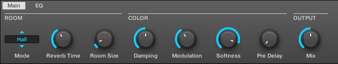
The Reverb in the Control area (Main page depicted).
Main page
Element | Description |
|---|---|
ROOM Section | |
Mode | Allows you to choose one of three basic modes of Reverb: Room, Hall, and Plate (default: Room). |
Reverb Time | Adjusts the reverb decay time. Turn clockwise to increase decay. Available values range can be adjusted in seconds from 0.5s to 20.2s (default: 2.2s). |
Room Size | Adjust the size of the simulated room. Turn clockwise to increase the perceived size of the room and reverb reflections. Available values range from 0.0 to 100.0% (default: 10.0%). |
COLOR Section | |
Damping | Adjusts damping of the high frequencies in the reverb signal. Damping refers to the rate at which the high frequencies decay. This effect causes the sound to become gradually muffled and warmer. Available values range from 0.0 to 100.0% (default: 50.0%). |
Modulation | Sets the modulation amount. A value of 0 turns the delay modulation off. Available values range from 0.0 to 100.0% (default: 40.0%). |
Softness | Alters the balance between early reflections and the late reverb tail. It also changes the amount of diffusion present. It allows you to soften the attack of the reverb and push it more into the background, so it doesn't muddy the dry sound so much. Available values range from 0.0 to 100.0% (default: 90.0%). |
Pre Delay | Adjusts the initial delay between the original signal and the first reverberant sound. At higher values this can also be used in many creative ways. Available values can be adjusted in milliseconds from 0.0ms to 250.0ms (default: 0.0ms). |
OUTPUT Section | |
Mix | Adjusts the ratio between the effect (wet) signal and original (dry) signals. Available values range from 0.0 to 100.0% (default: 50.0%). |
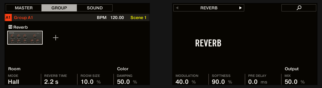
The Reverb Hall on the controller.
EQ page
The EQ page contains parameters to adjust the EQ of the reverb.
Element | Description |
|---|---|
EQ Section | |
High Cut | Adjusts the high frequencies in the reverberated signal. Available values range in kilohertz from 20.0 kHz to 2.0 kHz (default: 20.0 kHz). |
Low Shelf | Adjusts the low-frequency content in the reverberated signal. Available values range in decibels from -0.0 dB to -12.0 dB (default: -0.0 dB). |
Plate Reverb
This effect emulates a plate reverberator. Partly inspired by a legendary plate reverb system, this efficient reverb effect can be used in numerous situations. Its controls make the Plate Reverb easy to use while still flexible and unique sounding. The Plate Reverb is the best choice if a vintage metallic sound is desired. It is particularly good for vocals, but popular for other material as well, such as snare drums.
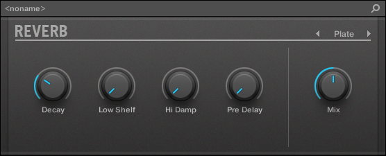
The Plate Reverb effect in the Plug-in Strip.
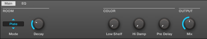
The Plate Reverb in the Control area.
Parameter | Description |
|---|---|
MAIN Section | |
Mode | Allows you to choose one of three basic modes of Reverb: Room, Hall, and Plate (default: Room). |
Decay | Adjusts the damping of the plate, which directly affects the decay time of the reverb. |
EQ Section | |
Low Shelf | Controls the low-frequency content in the reverberated signal. |
High Damp | Adjusts the damping of the high frequencies in the reverberated signal. |
Pre Delay | Adjusts the time between the original signal and the early reflections. |
OUTPUT Section | |
Mix | Mix lets you adjust the amount of the effect in relation to the dry original audio signal. |
The Reverb Plate on the controller.
Delays
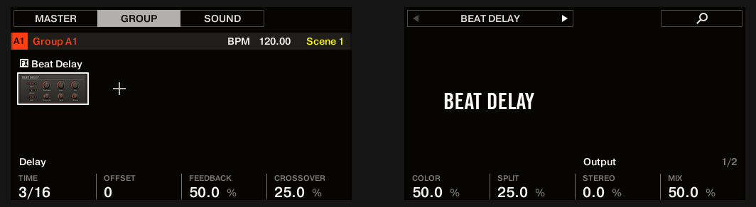
Beat Delay
The Beat Delay specializes in creating delays that are synced to the tempo. If you wonder how this sounds, load up the Project “Big Stream” from the Maschine factory library: the Beat Delay is used in various Groups here and offers many rhythmic sonic possibilities. Please note that in the Control area and on your controller, the Beat Delay parameters are spread over two pages.
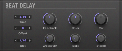
The Beat Delay panel in the Plug-in Strip.
Main page
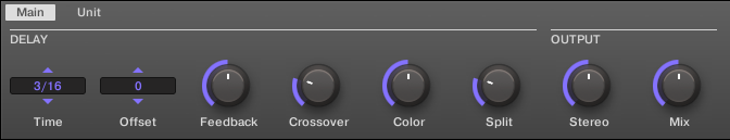
The Beat Delay in the Control area: Main page.
Parameter | Description |
|---|---|
DELAY Section | |
Time | The Time parameter defines the delay length in note values. The available values depend on the unit defined by the Unit parameter on the Unit page (refer to below). They range from half a unit to 16 units. |
Offset | This parameter is used to shift the start of the delay in relation to the tempo. |
Feedback | Adjusts the amount of output signal fed back into the input. Higher values produce more copies of the signal and longer decays. |
Crossover | Allows for panning the feedback signal rhythmically in the stereo field. |
Color | Defines the basic frequency of the feedback circuit: lower values result in a deeper sound, whereas higher values brighten the sound. |
Split | Controls the difference in frequency between the left and right channels. At full left, this control is deactivated. |
OUTPUT Section | |
Stereo | This parameter widens the stereo field of the effect. For example, values go from -100.0 % to 100 %, and negative values inverse the stereo field of the effect. |
Mix | Mix lets you adjust the amount of the effect in relation to the dry original audio signal. |
The Beat Delay on the controller: MAIN page.
Unit page
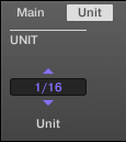
The Beat Delay in the Control area: Unit page.
Parameter | Description |
|---|---|
UNIT Section | |
Unit | Defines the unit used by the Time and Offset parameters on the Main page. |
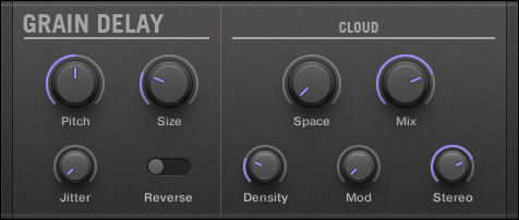
Grain Delay
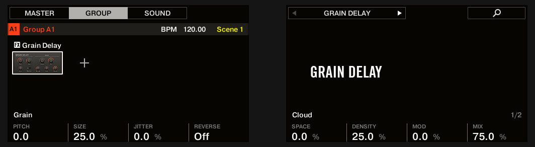
By chopping the input into small “grains” and rearranging them as a cloud, the Grain Delay is useful for creating ambient textures. Increase Size, Space and Density to quickly transform any sound into an evolving ambient texture. As a unique experimental effect, it is best experienced firsthand. Please note that in the Control area and on your controller, the Grain Delay parameters are spread over two pages.
The Grain Delay panel in the Plug-in Strip.
Main page
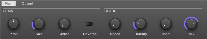
The Grain Delay in the Control area: Main page.
Parameter | Description |
|---|---|
GRAIN Section | |
Pitch | Determines the pitch of the grains: low values result in a deep, slowly repeating grain. High values speed up the grain, making it sound faster and higher. |
Size | Defines the length of the grains. |
Jitter | Introduces artifacts into the grains. |
Reverse | Produces a reverse playback of the grain. |
CLOUD Section | |
Space | Determines the spacing between the grain clouds: the higher the value, the bigger the space between the clouds. |
Density | Creates a more “dense” cloud: higher values create feedback-like effects. |
Mod | The amount of modulation introduced to the grain cloud. |
Mix | Lets you adjust the amount of the effect in relation to the dry original audio signal. |
The Grain Delay on the controller: Main page.
Output page
The Grain Delay in the Control area: Output page.
Parameter | Description |
|---|---|
OUTPUT Section | |
Stereo | This parameter widens the stereo field of the effect. Values go from 0 % (no stereo) to 100 % (full stereo). |
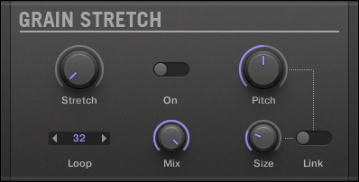
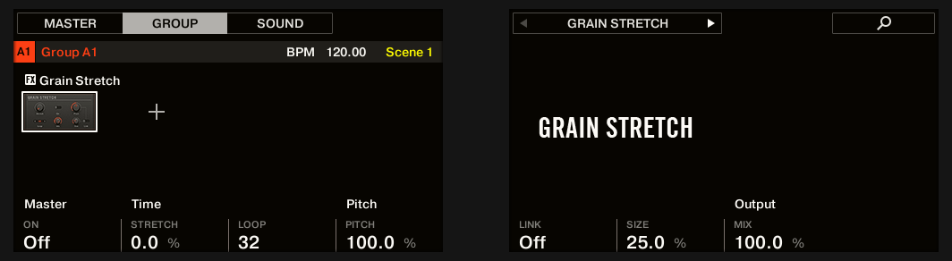
Grain Stretch
The Grain Stretch effect uses granular synthesis to manipulate the speed and pitch of the incoming signal.
The Grain Stretch panel in the Plug-in Strip.
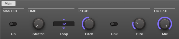
The Grain Stretch in the Control area.
Parameter | Description |
|---|---|
MASTER Section | |
On | Enables the effect. Every time this control is switched on, the Grain Stretch effect buffers incoming audio for 32 x 1/16th step. |
TIME Section | |
Stretch | Defines the time-stretch amount. Set to 50.0 % for half speed. |
Loop | Sets a loop length, in 1/16th steps. |
PITCH Section | |
Pitch | Adjusts the pitch of the grains. |
Link | When on, grain size is corrected by the pitch. |
Size | Adjusts the size of the grains. |
OUTPUT Section | |
Mix | Mix lets you adjust the amount of the effect in relation to the dry original audio signal. |
The Grain Stretch on the controller.
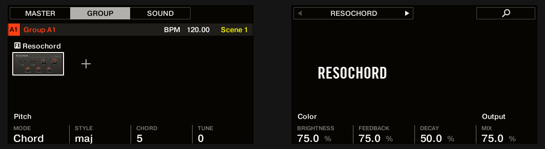
Resochord
The Resochord is a bank of 6 comb filters, each of which is individually tuned according to the selected chord. The results are most effective with non-melodic content (like drums) as the Resochord will print its own harmonic content on to any input material.
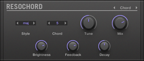
The Resochord panel in the Plug-in Strip.
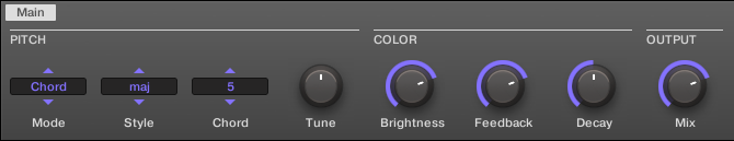
The Resochord in the Control area.
Parameter | Description |
|---|---|
PITCH Section | |
Mode | Here you can select between the two modes of the Resochord: Chord and String. In Chord mode, the 6 combs are tuned according to various chords. In String mode, the 6 combs are centered around one frequency and can be spread for an intense chorus-like effect. Depending on your selection the other parameters in the Pitch area will change. |
Spread (String mode) | Allows you to define how big the difference in tuning is between combs. |
Style (Chord mode) | You can select between different chord-styles such as minor or major. |
Chord (Chord mode) | Here you can choose from different chords to be applied to your audio signal. |
Tune | It allows you to transpose the Resochord in semitones. |
COLOR Section | |
Brightness | This is to determine the basic sound characteristic of the Resochord: higher values will brighten the sound by adding high frequencies. |
Feedback | Adjusts the amount of output signal fed back into the input. |
Decay | With Decay you adjust how fast the Resochord fades out. |
OUTPUT Section | |
Mix | Mix lets you adjust the amount of the effect in relation to the dry original audio signal. |
The Resochord on the controller.
Distortion effects
Distortion
The Distortion effect contains two modes of distortion: Mullholland and Analog.
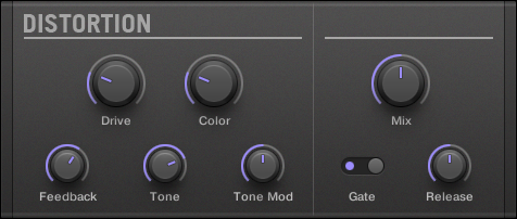
The Distortion panel in the Plug-in Strip.
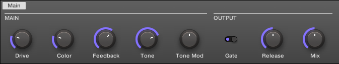
The Distortion in the Control area.
Mullholland mode
Mullholland mode combines overdrive, feedback and modulation, this produces a heavy distortion/fuzz effect, comparable to distortion stomp-boxes for guitars. This effect is special because of the feedback it creates.
Parameter | Description |
|---|---|
MAIN Section | |
Mode | Select a distortion type: Mullholland or Analog. |
Drive | Determines the basic amount of distortion. |
Color | At lower settings, the general sound is a bit more muffled; the higher the settings, the brighter it sounds. |
Feedback | Adjust the amount of output signal fed back into the input. |
Tone | General tonal characteristic of the feedback signal. |
Tone Mod | Modulation introduced in the feedback signal. |
OUTPUT Section | |
Mix | Mix lets you adjust the amount of the effect in relation to the dry original audio signal. |
GATE Section | |
Gate | The Gate button is used to cancel out feedback loops introduced by high Feedback settings. |
Release | This parameter determines how fast the distorted sound dies down when the Gate is activated. |
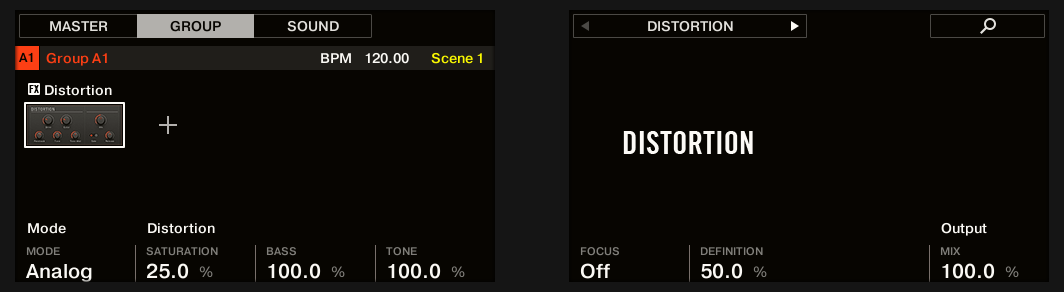
Analog distortion
Analog mode adds grit to Drums and Percussion, Lead Synths and Guitars.
Parameter | Description |
|---|---|
MODE Section | |
Mode | Select a distortion type: Mullholland or Analog. |
DISTORTION Section | |
Saturation | Sets the amount of saturation applied to the signal. Available values range from 0.0 to 100.0% (default: 25.0%). |
Bass | Attenuates the low frequencies of the distortion effect. Available values range from 0.0 to 100.0% (default: 100.0%). |
Tone | Sets the frequency for the high cut filter. Filtering the harmonically rich distorted signal produces a softer tone. Available values range from 0.0 to 100.0% (default: 100.0%). |
Focus | Switches the frequency range of the processed signal, pulling it slightly further forwards in the mix. The effect is more pronounced when Definition is set to lower values. |
Definition | Determines how pronounced the distortion effect is. Available values range from 0.0 to 100.0% (default: 50.0%). |
OUTPUT Section | |
Mix | Mix lets you adjust the amount of the effect in relation to the dry original audio signal. Available values range from 0.0 to 100.0% (default: 100.0%). |
The Distortion on the controller.
Lofi
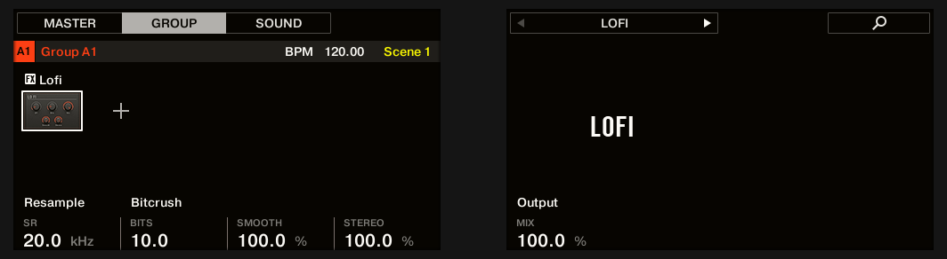
The Lofi effect reduces the bit depth (or bit resolution) and Sample rate of the audio signal for an interesting “vintage” effect at subtle settings, and heavy digital distortion at extreme settings.
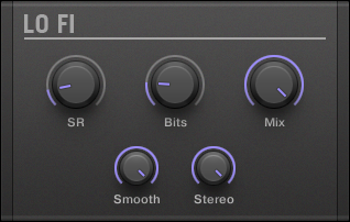
The Lofi panel in the Plug-in Strip.
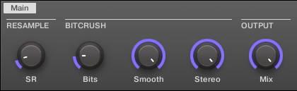
The Lofi in the Control area.
Parameter | Description |
|---|---|
RESAMPLE Section | |
SR | SR stands for Sample Rate and ranges from CD-quality (44.1 kHz) to 99.5 Hz which results in a hissy crackle. |
BITCRUSH Section | |
Bits | Introduces a distortion based on bit reduction. |
Smooth | Reduces the aliasing introduced by the Lofi effect. |
Stereo | Widens the stereo field of the effect. |
OUTPUT Section | |
Mix | Mix lets you adjust the amount of the effect in relation to the dry original audio signal. |
The Lofi on the controller.
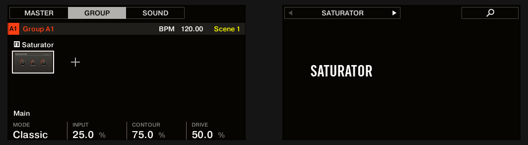
Saturator
The Saturator is a flexible tool allowing you to apply various types of saturations to your signal. The Saturator offers three modes: Classic (legacy mode), Tape, and Tube. You can select the desired mode via the Mode selector. Since the three modes provide different sets of parameters, each of them is described separately below.
The Saturator panel (here in Tube mode) in the Plug-in Strip.
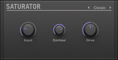
Classic mode
The Classic mode is the legacy mode. It combines compression and saturation to increase the overall loudness and add additional harmonics.
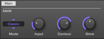
The Saturator in Classic mode in the Control area.
Classic mode – parameter | Description |
|---|---|
MAIN Section | |
Mode | Selects between Classic, Tape, and Tube saturation modes. All other parameters vary according to the mode selected here. |
Input | Controls the input gain of the effect. Increasing Input will also increase the amount of compression performed on the audio signal. |
Contour | Determines how closely the Saturator responds to the input volume. Higher values create a more distorted sound. |
Drive | Adjusts the amount of distortion introduced by the Saturator. |
The Saturator in Classic mode on the controller.
Tape mode
The Tape mode emulates the soft compression and pleasant saturation induced by recording to analogue magnetic tapes. It can be used lightly to add warmth and coloring to the sound, or heavily to add aggressive distortion.
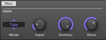
The Saturator in Tape mode in the Control area.
Tape mode – parameter | Description |
|---|---|
MAIN Section | |
Mode | Selects between Classic, Tape, and Tube saturation modes. All other parameters vary according to the mode selected here. |
Input | Controls the input gain of the effect. This affects the amount of tape distortion and compression. |
Contour | Controls the high frequency roll-off starting frequency. Frequencies above this point will be attenuated. |
Drive | Controls the low frequency boost/cut of the effect. |
Tube mode
The Tube mode emulates the smooth saturation of overdriven tube amplifiers. It is equipped with a feedback-driven dynamic compression and an additional EQ section allowing you to fine adjust the frequency content to be processed.
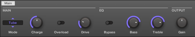
The Saturator in Tube mode in the Control area.
Tube mode – parameter | Description |
|---|---|
MAIN Section | |
Mode | Selects between Classic, Tape, and Tube saturation modes. All other parameters vary according to the mode selected here. |
Charge | In Tube mode the Saturator provides a negative feedback loop that attenuates the level at the Saturator’s input according to the amount of low frequencies at its output. This notably prevents the bass content “polluting” the saturation. The Charge parameter allows you to adjust the amount of feedback. At 0 (full left) the feedback loop is deactivated. Increase the Charge value to strengthen the effect. Higher values additionally generate an interesting compression-like effect. |
Overload | Boosts the low frequencies of the input signal. Used together with the Charge parameter (see above) it provides you with a powerful tool to produce a richer, fatter sound. |
Drive | Adjusts the level of the input signal. This directly affects the amount of tube distortion. |
EQ Section | |
Bypass | Enable this button to bypass the EQ section. |
Bass | Adjusts the level of the low frequency band. |
Treble | Adjusts the level of the high frequency band. |
OUTPUT Section | |
Gain | Adjusts the output level of the effect. Use this to compensate for changes in volume caused by input gain and signal compression. |
Perform FX
Designed for spontaneous, tactile control in recording or live performance, these eight complex multi-effects alter motion, space, dynamics, and more for added expression.
Filter: The Filter is a raw-sounding, analog-modeled LP/BP/HP filter with additional saturation parameters and resonance that can be pushed into self-oscillation. For more information see section Filter.
Flanger: The Flanger is a comb filter effect. It can behave like a standard flanger or phaser but can also go pretty wild and sound more like a creative delay if you push the decay and delay time. Various tone-shaping controls are available. For more information see section Flanger.
Burst Echo: The Burst Echo is a warm, versatile echo with plenty of character. It's great as a dub echo but can also be used for quite extreme sound design. For more information see section Burst Echo.
Reso Echo: The Reso Echo is a crazy psychedelic echo which can be tightened up into a punchy resonator. For more information see section Reso Echo.
Ring: Based on a bank of ring modulators, the Ring effect adds a bell-like quality to melodic sound sources. An additional plate reverb lets you pick out individual notes with your finger and have them ring out for several seconds. For more information see section Ring.
Stutter: Stutter is a beat-mangling effect, great for adding glitches and fills to drum patterns and more. For more information see section Stutter.
Tremolo: Tremolo is a tremolo/vibrato effect, useful for adding expression and movement on the fly. For more information see section Tremolo.
Scratcher: At its most basic, Scratcher allows you to apply a turntable “brake” to the incoming signal and then scratch it, as if on vinyl. But an additional pitch shifter delay, linked to the Smart Strip position, adds a wealth of sonic possibilities, from simple thickening to alien-sounding sweeps. For more information see section Scratcher.
For information on how to control a Perform FX parameter using the Smart Strip, refer to Perform mode.
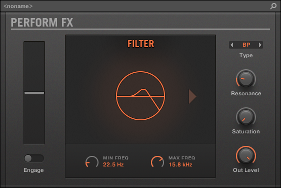
Filter
An analog-modeled High, Low, and Band-pass filter capable of yielding raw, natural-sounding results using saturation and resonance. Roll off the highs for a thick, murky veil, or use the resonance to create sounds that float into self-oscillation infinity.
Filter Perform FX in the Plug-in Strip.
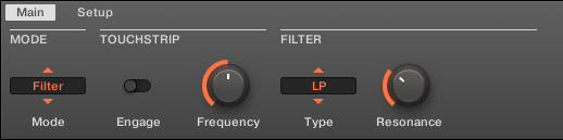
Filter Perform FX in the Control area.
Main page
Parameter | Description |
|---|---|
MODE Section | |
Mode | Select an effect. |
TOUCHSTRIP Section | |
Engage | Activates the filter. |
Frequency | Sets the cutoff frequency according to the min/max range parameters. |
FILTER | |
Type | Selects from Low Pass, Band Pass and High Pass modes. |
Resonance | Sets the resonance of the filter. Values over 100% will lead to self-oscillation—be careful! Turn down the Output Gain (and turn up the Saturation to compensate) in order to avoid extremely loud ringing. Note that the resonance will sound more pronounced at lower saturation settings and vice versa. |
Setup page
Parameter | Description |
|---|---|
RANGE Section | |
Min. Freq | Sets the lower limit for cutoff frequency. |
Max. Freq | Sets the upper limit for cutoff frequency. |
SATURATION Section | |
Saturation | Sets the input gain of the filter. |
Out Level | Sets the output gain of the filter. |
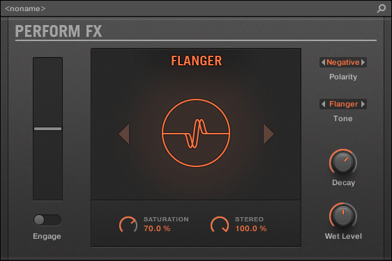
Flanger
A comb filter effect with more than a few tricks up its sleeve. Get performance-ready flanger or phaser effects, or expose its wild side – setting higher decay and frequency values unleashes ping-pong delay-like flutter effects.
Flanger Perform FX in the Plug-in Strip.
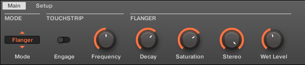
Flanger Perform FX in the Control area.
Main page
Parameter | Description |
|---|---|
MODE | |
Mode | Select an effect. |
TOUCHSTRIP | |
Engage | Activates the effect. |
Frequency | Controls the volume of the comb filter. |
FLANGER | |
Decay | Controls the decay time. |
SATURATION | Controls the saturation in the feedback path, producing a dirtier, compressed sound. |
STEREO | Controls the stereo spread of the effect. |
Setup page
Parameter | Description |
|---|---|
COLOR | |
Polarity | Flips the phase of the signal in the feedback loop. Negative polarity lowers the pitch by an octave and produces a slightly hollower sound. |
Tone | Offers the choice between Flanger mode, essentially a straightforward comb filter or short delay, and Phaser mode, which shifts the phase of the signal in the feedback loop to produce a more rounded, hollow tone. |
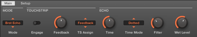
Burst Echo
A warm, versatile echo with plenty of character, designed for spontaneous splashes of echo. Strong, responsive attacks that taper off into hazy trails are perfect for dub and can also be tweaked for more extreme sound design.
Burst Echo Perform FX in the Plug-in Strip.
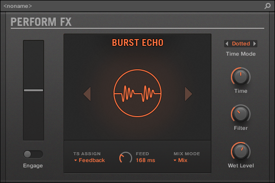
Burst Echo Perform FX in the Control area.
Main page
Parameter | Description |
|---|---|
MODE | |
Mode | Select an effect. |
TOUCHSTRIP | |
Engage | Activates the effect. When activated, feeds a burst of signal into the effect according to the length set by the Feed parameter. |
TS Assign | Assigns the control to Feedback or Time. Feedback: Sets the delay feedback when the effect is activated. The feedback is reduced when the effect is disengaged. |
ECHO | |
Time | Controls the delay time, either continuously or in quantized divisions according to the Time Mode. |
Time Mode | Sets the rhythm mode of the delay, either in quantized note divisions (Straight/Dotted/Free) or unquantized (milliseconds). |
Filter | Adjusts the LP and HP filter in the feedback loop. At 0%, the filter is fully open. At higher values, the HPF frequency increases and LPF frequency decreases for more aggressive filtering. |
Wet Level | Adjusts the volume of the delayed signal. |
Setup page
Parameter | Description |
|---|---|
ROUTING | |
Mix Mode | Mix mode sets the routing of the signal:
|
Feed | Sets the length of the burst of audio to feed into the delay input whenever the effect is initially activated. Shorter burst lengths (e.g. 100-150ms) are useful for picking out notes or drum hits. Longer burst lengths (up to a second) can be used to repeat musical phrases. Set to maximum (>99%), the feed is continuous, deactivating burst mode entirely and simply feeding the delay whenever the effect is on. |
Reso Echo
A complex resonant echo with advanced feedback and saturation that verge on psychedelic tendencies. Echoes range from a tight, punchy resonant hum to ambiguous howling sounds from another dimension.
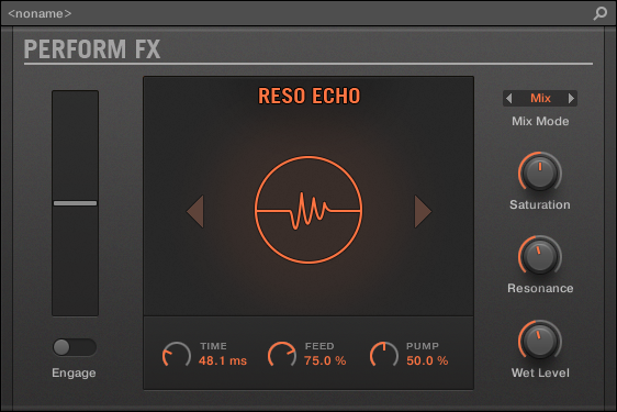
Reso Echo Perform FX in the Plug-in Strip.
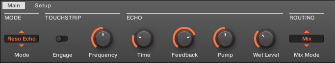
Reso Echo Perform FX in the Control area.
Main page
Parameter | Description |
|---|---|
MODE | |
Mode | Select an effect. |
TOUCHSTRIP | |
Engage | Activates the effect. |
Frequency | Controls the frequency of the filters in the filter bank, altering the tonality of the signal. |
ECHO | |
Time | Sets the delay time. |
Feedback | Sets the delay feedback. |
Pump | Controls the amount of compression applied to the feedback loop. |
Wet Level | Controls the volume of the delayed signal. |
Mix Mode | Sets the routing of the signal: - In Mix mode, the dry signal is passed unprocessed and the wet signal is added on top according to the Wet Level parameter. - In Insert mode, the dry signal is processed with a filter and the wet signal is added on top. The Wet Level parameter is an output level control for the whole effect while engaged. - In Wet Only mode, the dry signal is muted entirely, which is useful for placing the effect on a send. |
Setup page
COLOUR | |
Saturation | Controls the amount of saturation applied to the feedback path. |
Resonance | Controls the resonance of the filters in the filter bank. More resonance emphasizes the "singing" effect. |
Ring
Built on a carefully selected bank of ring modulators, Ring adds a bell-like quality to melodic sound sources. Using the additional plate reverb, tweak a knob or Smart Strip to hand-pick individual notes and keep them ringing into the stratosphere.
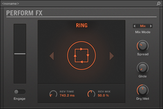
Ring Perform FX in the Plug-in Strip.
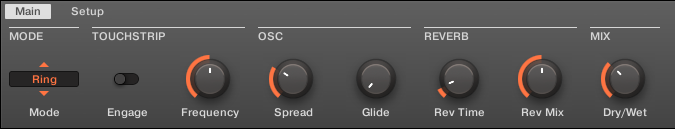
Ring Perform FX in the Control area.
Main page
Parameter | Description |
|---|---|
MODE | |
Mode | Select an effect. |
TOUCHSTRIP | |
Engage | Activates the effect. |
Frequency | Controls the frequency of the ring modulators. |
OSC | |
Spread | Controls the frequency spread of the ring modulators. At low Spread values, the ring modulators converge to a single modulation frequency. At higher Spread values, the oscillator frequencies become further apart. |
Glide | Sets the smoothing rate of the control position, allowing for pitch slides as you activate different values. |
REVERB | |
Rev Time | Controls the decay time of the plate reverb. |
Rev Mix | Controls the dry/wet mix of the plate reverb. |
MIX | |
Dry/Wet | Controls the dry/wet mix of the overall effect. |
Setup page
Parameter | Description |
|---|---|
ROUTING | |
Mix Mode | Mix mode sets the routing of the signal:
|
Stutter
Turn the intensity up, and down again with Stutter. This beat-mangling effect adds creative dynamics like glitches, fills, and expressive pitch-bending crescendos to drum patterns and more.
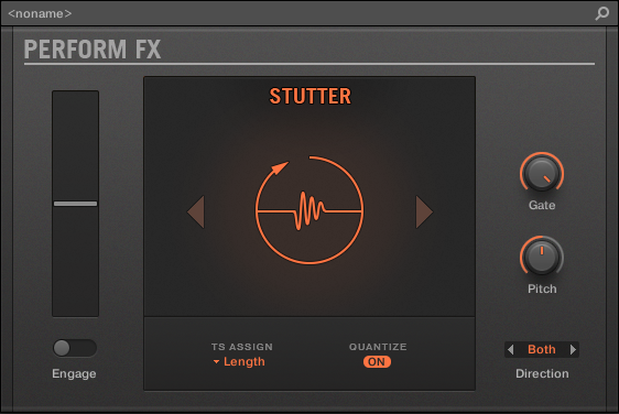
Stutter Perform FX in the Plug-in Strip.
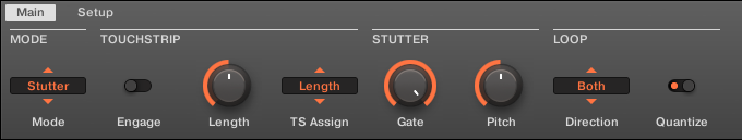
Stutter Perform FX in the Control area.
Main page
Parameter | Description |
|---|---|
MODE | |
Mode | Select an effect. |
TOUCHSTRIP | |
Engage | Controls a hard bypass. Activating the control commences looping, releasing the control bypasses the effect. |
Length | Can be assigned to Length (loop length, by default) or Pitch (relative pitch) using TS Assign. |
TS Assign | Assigns the control to Length or Pitch. |
STUTTER | |
Gate | Applies a volume envelope to the loop, exaggerating the "stutter" effect, especially at short loop lengths. Setting the parameter to 100% effectively disables the envelope whereas the gating is most extreme at 0%. |
Pitch | Parameter controls playback pitch (relative to pitch when the effect is engaged) when the controls are assigned to Length, and the Length parameter controls loop length when the control is assigned to Pitch. Otherwise each of these parameters has no effect and is respectively hidden. |
LOOP | |
Direction | Controls the looping direction—Forward (always forward), Reverse (always reverse) or Both. In Both mode, direction is forwards by default on engage and whenever the most recent control movement was upwards, or reverse whenever the most recent control movement was downwards. The Direction parameter is available only when the TS Assign is set to Length. |
Quantize | Quantizes the loop length and start point to the song position and tempo. When Quantize is off, the loop length is continuously variable and measured in milliseconds, and no quantization takes place. Quantization is especially meaningful if direction is set to Reverse or Both, since it's during reverse playback where a poorly timed loop will sound completely off-time. |
Tremolo
A no-frills tremolo and vibrato effect that’s perfect for creating motion and wobble on the fly. Instantly add expression with multiple modes, Rate, and Depth ranges, and use the Stereo knob to create auto-pan motion effects.
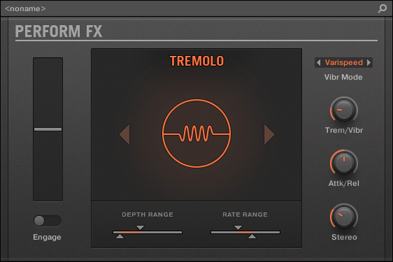
Tremolo Perform FX in the Plug-in Strip.
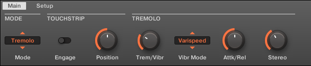
Tremolo Perform FX in the Control area.
Main page
Parameter | Description |
|---|---|
MODE | |
Mode | Select an effect. |
TOUCHSTRIP | |
Engage | Enables and disables the effect. |
Position | Controls the tremolo and vibrato rate and depth, within the ranges defined by the Min and Max parameters on the second page. |
TREMOLO | |
Trem/Vibr | Controls the balance between tremolo (modulation of amplitude) and vibrato (modulation of frequency/pitch). |
Vibr Mode | Sets the vibrato mode. Two are available: Varispeed, which modulates the playback speed of the audio, much like moving the pitch control on a turntable or tape player, and Freq Shift, which uses a modulated frequency shifter. Freq Shift produces a somewhat detuned sound due to the nature of the frequency shifting—low frequencies are more audibly shifted than high frequencies. Varispeed scales pitches evenly across the audible range, but it introduces small fluctuations in timing. |
Attk/Rel | Controls the speed at which the effect comes on after turning the effect on and tails off after releasing the effect. |
Stereo | Controls the stereo width of the modulation. |
Setup page
Parameter | Description |
|---|---|
DEPTH RANGE | |
Depth Min | Controls the amplitude of the modulation when the parameter position is set to 0%. |
Depth Max | Controls the amplitude of the modulation when the parameter position is set to 100%. |
DEPTH RANGE | |
Rate Min | Controls the rate of the modulation when the parameter position is set to 0%. |
Rate Max | Controls the rate of the modulation when the parameter position is set to 100%. |
Scratcher
Scratcher warps your sounds with turntable motion effects that can get other-worldly. Apply a ‘brake’ to a sound, then scratch with it – just like on vinyl. Or use the pitch shifter delay to thicken the sound and create alien-sounding sweeps.
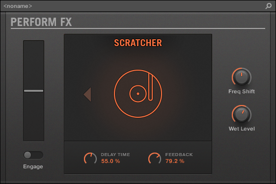
Scratcher Perform FX in the Plug-in Strip.
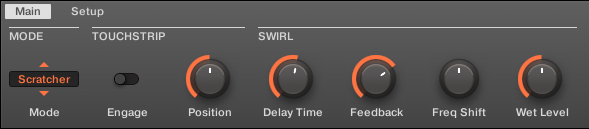
Scratcher Perform FX in the Control area.
Main page
Parameter | Description |
|---|---|
MODE | |
Mode | Select an effect. |
TOUCHSTRIP | |
Engage | Engages the turntable brake, enabling scratch control. When released, the effect is bypassed entirely. |
Position | Controls the brake speed (higher = slower brake), the scratch position (higher = forward) and the delay time (higher = longer delay time). |
SWIRL | |
Delay Time | Controls the delay time range. Longer values produce a delay effect. Shorter values result in a comb filtering effect. The Position parameter acts as a further scale factor on this delay time. |
Feedback | Controls the delay feedback. |
Freq Shift | Controls a frequency shifter in the delay feedback loop. At 12 o'clock, the frequency shifter is deactivated. Swirling, alien and metallic sounds can be made by enabling the frequency shifter and increasing the feedback. |
Wet Level | Controls the level of the delay effect. |