Oscillator Section
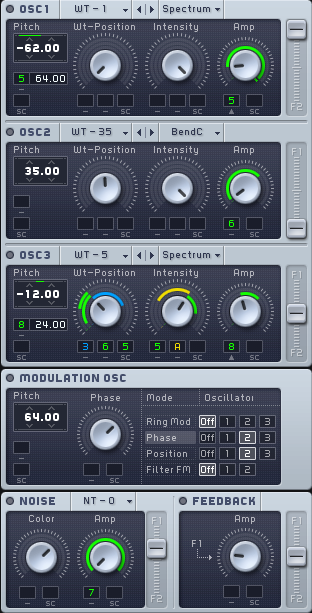
The generation of sound in MASSIVE begins from the Oscillator Section, which can be found at the left-hand side of the interface. It includes three wavetable oscillators, a modulation oscillator that can be used to modulate any or all of these wavetable oscillators, a noise generator, and a feedback section.
Wavetable oscillators
Three wavetable oscillators form the basis of sound generation in MASSIVE. In this type of synthesis, numerical representations of various types of basic waveforms are stored in wavetables. Instead of directly computing a sine wave, for example, a wavetable oscillator uses a digital representation of a sine wave stored in memory. This synthesis technique is similar to sampling: instead of an actual audio source, a digital representation or “recording” of it is used. Selecting a wavetable is like selecting a waveform on a classic analog synthesizer, like a sine wave or sawtooth wave.
MASSIVE uses a particular form of wavetable: each wavetable contains not only one waveform, but at least two of them. Think of these wavetables in two dimensions. The horizontal axis represents time, and the “recorded” waveforms run from left to right on the table just as in any sample editor: playback starts from the left, and when one complete waveform cycle has been played from left to right, the playback jumps back to the beginning at the left to loop the waveform.
Along the vertical axis, on the other hand, there are different waveforms one above another, like the tracks in a multi-track sequencer: at the bottom there is one waveform and at the top there is another one. Between them are a series of intermediate waveforms that gradually morph from the bottom waveform shape to the top.
The vertical position can be controlled to adjust the sound by using the Wt-Position (wavetable position) control. For instance, imagine a wavetable where you have a pulse waveform shape at the “bottom” and a sawtooth waveform shape at the “top.” Turning the Wt-position control from left to right now slowly morphs the waveform shape from pulse to sawtooth.
This method of synthesis allows for highly flexible shifting combinations of various waveforms as each oscillator can be made to gradually morph from one type of waveform to another.
In order to get a feel for the kinds of sounds you can create with wavetables, just load a wavetable into one of the oscillators and start tweaking the oscillator controls. You’ll immediately hear the sonic results, and you’ll be able to get a feel for what the controls do very quickly.
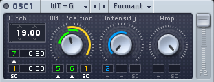
Wavetable Controls
Each oscillator has three knobs and two popup menus that control its functioning.
You can choose the specific wavetable to use for each oscillator by using the popup menu at top left. Here you will see a list of all the different wavetables you can choose from, a wide variety of different choices and sounds. You can also go through the wavetables in order by using the Prev and Next buttons here.
You can control the selection of the specific waveform to be played from the oscillator by using the Wt-Position Control Knob. Turning this knob scans through all of the waveforms included in the wavetable. The number of individual waveforms represented in each table can range from only 2 to as many as 128 or more.
Complex sweeping effects can be obtained by routing one of the modulation sources in MASSIVE to control the Wavetable Position knob, thus causing the waveform to constantly morph and change. This is the kind of synthesis technique associated with classic wavetable synthesizers such as the Waldorf PPG Wave.
Try modulating the Wavetable Position knob with one of MASSIVE’s LFOs and you can hear how the sound morphs from one waveform to another. Here’s how to set it up:
Click on the Modulation Handle following the name of the Modulation Source you want to use. Then drag the mouse towards the Wavetable Position knob and release the button over one of the Modulation Slots below it.
After making the assignment, you will see a small green numeral appear in the Modulation Slot under the Wt-position knob. The numeral indicates which LFO has been assigned to the slot.
Now you can adjust the modulation range by clicking on the assigned modulator slot and dragging up or down. As you do so, you will see a colored ring appear around the Wt-position knob to indicate the active range of the modulation. Also make sure to turn up the Amp control in the LFO page itself to adjust the magnitude of effect.
The effect you will hear here depends primarily on which wavetable you have selected.
Even more complex overlapping phasing effects are possible by applying this same technique to more than one oscillator simultaneously!
The Pitch display allows you to tune the oscillator up or down in frequency, adjusting it by semitones and cents (hundredths of a semitone). Pitch can also be modulated by routing a modulation source to one of the modulation destination slots just below it, allowing you to create powerful vibrato and arpeggiation effects.
To create a rapid sequence/arpeggio effect, route the Stepper modulator to pitch and assign it to a wider pitch range. First click on the Modulation Handle to the right of the Stepper in the Center Window, then drag the cursor to the Modulation Slot under the Pitch Display and release. You will see a small green numeral appear corresponding to the Stepper. Then click and drag on the small display which appears to the right, indicating the range over which the Stepper modulator will be active. (You also need to set the Amp control in the Stepper Page itself, this sets the amount of modulation sent from the Stepper.) This will cause MASSIVE to play a looping sequence of distinct pitches every time you play a MIDI note. (See also section Modulation Pages on modulation sources for more on the Stepper and how it works.)
The Intensity knob for each oscillator gives you a number of ways of shaping the wavetable read-out, depending on which Oscillator mode is selected in the right-hand popup menu.
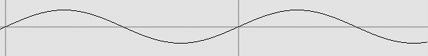
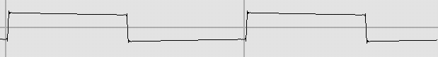
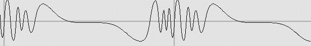
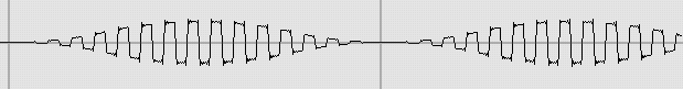
Several different modes are available including Spectrum, Formant, and three Bend modes. The default selection is Spectrum mode. In this mode the Intensity control reduces the higher-frequency harmonics heard in the selected waveform. This functions similarly to a low-pass filter cutoff, even though the algorithm behind it is different from a standard filter design. This is illustrated below: the upper image displays a wave with minimum Intensity setting; the lower one has a maximum Intensity value. As you can see, when turning down the Intensity value, the square wave gradually becomes a sine wave, i.e. only the fundamental sine wave remains.
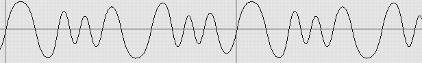
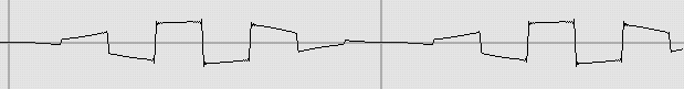
When any of the Bend modes are chosen, the Intensity knob will shape the readout curve of the wavetables. Normally, the wavetable is read out at constant speed. With the Bend modes you can raise and lower the readout speed depending on the position within the wavetable, e.g. slow at the beginning and fast at the end. Visually, this is displayed below, taking BendB mode as an example.
The middle image (Intensity knob at mid position) shows the unaltered waveform.
The upper image (Intensity turned to the left) visualizes a fast readout at the beginning and end of the waveform, i.e. the wave is compressed at the ends while it is stretched in the middle
The lower image shows the inverse effect (Intensity turned to the right). Here, the central part is compressed while the ends are stretched.
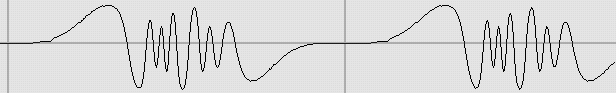
BendA mode only uses the two upper settings, i.e. the Intensity knob only morphs between the upper image (controller at the left) and the middle image (controller at the right). The third bend mode, finally, only interpolates between the middle image (Intensity at the left) and the lower image (Intensity at the right).
The sonic result of these bend modes depends completely on the wavetable you have selected; it is impossible to describe the effect in general. Just keep in mind that you can always use the bend modes to vary the basic waveforms provided with MASSIVE. Some wavetables also react in very interesting ways to modulation of the Intensity knob. This can cause very subtle changes of the sound’s frequency spectrum.
When Formant mode is chosen, Intensity controls the additional transposition of waveform formants. In practice this sounds a bit like the effect achieved with two oscillators where the leading oscillator synchronizes the following oscillator’s phase and the Intensity control then changes the transposition of the following oscillator. Try modulating the Intensity control with one of MASSIVE’s modulation sources: this will change the sound’s formant while the pitch still remains stable, simulating the sound of morphing vowels.
Amplification and Routing
The Amp knob controls the output volume of the oscillator. Use the three Amp controls (one for each oscillator) to control the relative balance of each oscillator within the overall sound. For example, try routing an LFO to the Amp knobs to modulate their values and cause the relative balance of the oscillators to shift and change as you hold down a single MIDI note. You can set this up like this:
First click the Modulation Handle of one of the LFOs in the Center Window and drag the cursor to one of the Modulation Slots under the Amp knob for OSC1, then release the mouse button. You should see a small colored numeral appear in the target Modulation Slot corresponding to the LFO that you have assigned.
Then, click on the numeral and drag the mouse up or down; you should see a colored band appear around the Amp knob. This indicates the range over which the LFO will modulate OSC1’s output amplitude. Also make sure to check the Amp control of the LFO page to adjust the magnitude of the effect.
To simultaneously modulate the output of a second oscillator, repeat the above procedure, only use a different LFO as the modulation source, and route it to modulate the Amp knob controlling the output of OSC2 instead of OSC1.
Now try playing a note on your MIDI keyboard to hear the result. You should be able to hear two distinct waveforms mixed in the sound, one from each oscillator. However, the relative balance of each waveform in the sound will gradually change, as the output amplitude of each oscillator is modulated by one of the LFOs.
You can create a tremolo effect by routing the same LFO to the Amp knobs of all of the oscillators at once.
Each oscillator also has a vertical Routing Fader at the right edge labeled F1-F2. This controls the balance of the oscillator’s output into either filter 1 or filter 2 or a mix of both. The filters in turn may be routed in either serial or parallel, or a combination of both (see more on this in section Filter Section on MASSIVE’s Filters below).
Modulation oscillator
This oscillator generates sine wave modulation source signals in the audible range. Its output can be used for ring, phase- and Wt-position modulation of the main oscillators, as well as a modulation source for filter frequency modulation (FM) effects. This oscillator is a perfect tool for sculpting aggressive, cutting sounds.
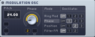
Note that you can set a distinct target in this section for each modulation type. You will see a different label on the control knob here in this section depending on which mode you currently have selected. However, note that there is still only one modulation oscillator, so if you change the pitch for the ring modulation, this will also affect the frequency of the filter’s modulation and so on.
Also, remember that the modulation oscillator can also be modulated itself in pitch and amount by all available modulation sources such as the envelopes and LFOs, allowing for even more complex modulated sounds. Each modulation mode can be affected by a different modulation source as well. For example, an envelope can control the amount of ring modulation on OSC1 while an LFO changes the amount of phase modulation on OSC2. Try using very slow LFO speeds to modulate this control; this will achieve very slowly changing, subtly morphing sounds.
By default, the modulation oscillator is also pitch tracked, which means that tonal playability of ring modulation sounds is easily achieved.
Ring Modulation
A well-known technique within electronic music since the 1950s. Its name is derived from early analog circuits, as the diodes were connected in a ring-like shape. Ring modulation combines two audio signals in a way such that their frequencies are interrelated, creating new frequency components in the signal; these are called sidebands. They can be defined as the sum and difference of the various frequency components of the two source signals. Practically speaking, ring-modulating one of MASSIVE’s main oscillators usually creates bell-like, metallic sounds. Try detuning the modulation oscillator when using the ring modulator; for example, tune the modulation oscillator up or down by a tritone (6 semitones) for some interesting results.
Phase Modulation
This modulation type is sonically equivalent to the familiar frequency modulation or FM synthesis technique. The modulation oscillator acts as the modulator while the main oscillator becomes the carrier. You can use the phase modulation capacities of MASSIVE to create classic bass sounds, for instance. Try modulating the modulation amount with a fast envelope, e.g. to create very high modulation amounts at the beginning that then decay rapidly. This will produce an initial click when the sound is triggered, increasing its rhythmic presence and clarity.
Position Modulation
A new and unique type of modulation, made possible by the design of MASSIVE’S new wavetable engine. The modulation is more audible the more the main oscillator’s wavetable differs from the modulation oscillator’s sine wave. By enhancing the differences of the waves you can make the main oscillator’s sound rougher. This can be used to establish signals that sound like a bowed (or blown) instrument that has some “surface noise” in its sound. Also try detuning or transposing the modulation oscillator to vary the effect.
Filter Frequency Modulation
Allows you to modulate the frequency of one of the filters with the Modulation Oscillator. Try setting up the Filter FM like this for some interesting bass sounds:
Set Filter 1 to be modulated by Filter FM by clicking on the appropriate box (1) in the Modulation Oscillator Section. Choose the Daft filter for this example.
Transpose the modulation oscillator down by one octave (12 semitones) by clicking and dragging with the mouse.
Now assign one of the Envelopes to modulate the oscillator: click on the modulation handle to the right of one of the Envelopes in the Center Window, move the cursor to one of the modulation handles under the Filter FM control and click again to make the assignment. Click and drag on the small blue numeral that appears here to set the modulation range.
Then try adjusting the controls on the Envelope like this: decrease the Attack Time Control and increase the Attack Level Control, then reduce the Decay time and increase the Decay level, then set the Sustain level to minimum.
This will create an initial click, especially effective for bass sounds.
Noise Section
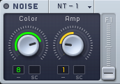
The Noise Section incorporates the sound of a noise generator into MASSIVE. There is a Noisetable popup menu at the top of the Noise Section allowing you to choose between different noise types (based on samples). The Color knob allows you to change the coloration of the noise by shifting the overall frequency spectrum upwards or downwards, while the Amp knob adjusts the volume. A Routing fader just like the ones in the Oscillator Section allows you to control how much of the output signal is sent to Filter 1 and Filter 2. The controls in the Noise Section can be modulated by any of the modulation sources.
Why would you want to add noise to a synthesizer sound? One reason is that some types of sounds, for example “unpitched” sounds such as electronic percussion and drums, are not based on a pitched waveform but rather a dense cluster of frequencies that are not harmonically related. The synthesis of these types of sounds requires a “noise generator” that produces all audio frequencies simultaneously, or some variation of this concept. Filtering the output of a noise oscillator can produce many variations on this type of sound. Many of the most popular synthesized drum sounds of all time, such as the Roland TR808 and 909, were created using this technique.
Here are some creative ideas for using the Noise section:
Try routing the Performer or Stepper modulation sources to control the Amp control in the Noise Section to create rhythmic hihats or other unpitched percussion effects.
Route an LFO to control the Amp Control of the Noise section and designate a relatively narrow modulation range. Use a fairly slow Rate setting on the LFO to create a subtly varied crackling environment, suitable for soft, intimate sounds.
Feedback Section
The Feedback Section allows you to re-route the signal from any of several different insert points back to the filter input. The point that the signal is routed back from can be chosen in the Routing Page of the Center Window (see section Signal Flow and Voicing). The signal’s source is then shown within the Feedback section.
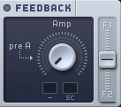
In the Feedback Section, you can adjust the level of output using the Amp level knob, and adjust the ratio of the output between filter 1 and filter 2 using the Routing Fader. The Amp knob has 2 modulation slots where you can attach a modulation source to change the output.
A typical case where you might want to make use of the Feedback Section is to create variable saturation effects. Try setting it up like this:
First click the Routing Page in the Center Window so you can see the diagram of MASSIVE’s signal flow.
Click one of the small FB icons in this diagram in order to select the source of the feedback signal. For this example, let’s choose the one at the top center of the diagram, a bit to the right of the Filter 1 icon.
To hear the feedback signal, turn up the Amp control in the Feedback Section. You’ll hear a heavier, saturated signal.
To create changing saturation effects, try assigning one of the modulation sources like an LFO to the Amp knob. Click on the Modulation Handle on the right part of the LFO tab and drag the mouse to the small black Modulation Slot under the Amp knob. Then click and drag on the small green numeral that appears to define the range of the Amplitude modulation. Also make sure to check the level of the Amp knob on the LFO page; if this is set to far left, you will hear no effect!
Note that due to the analog-style approach of the filter saturation, higher levels routed back through the feedback bus can change the filter behavior significantly and generate very different audio results through any effects that you might be using.
Another case where you might want to use the feedback bus would be to smooth out the resonance peak of a filter. Try smoothing the sound by increasing the feedback level back into the same filter bus like this:
First, in the Filter Section, choose the low-pass filter LP2 in Filter 1 by clicking on the popup menu in the header.
Now try turning the Resonance knob to about 50%. Move the Cutoff knob back and forth while playing a note on your MIDI keyboard. You should be able to hear the resonant peak around the cutoff frequency.
Now, as in the above example, click the Routing Page in the Center Window so you can see the diagram of MASSIVE’s signal flow. Then click one of the small FB icons in this diagram in order to select the source of the feedback signal. Again, choose the one at the top center of the diagram, a bit to the right of the Filter 1 icon.
Turn the Routing fader at the right edge of the Feedback Section all the way up, towards where it is labeled F1. In this position, all of the output of the Feedback Section will be routed back into the input of Filter 1.
To hear the feedback signal added in, turn up the Amp control in the Feedback Section. You may hear a heavier, saturated signal; however, the higher level of feedback signal as you increase the Amp knob will drive the filter circuit hotter and the increasing overtones in the sound will tend to mask the sharpness of the resonance.