The Center Window
At the center right of the main MASSIVE window, we find the Center Window. This area is the control center for two important parts of MASSIVE.
For one thing, the Center Window contains the controls and display for all of MASSIVE’s global parameters. These are visible on the six upper tabs, called the General pages.
In addition, the Center Window is the place where you can edit and assign all internal modulation sources. These are accessible via the eight lower tabs, called Modulation pages.

Note that both rows are of equal level and are not cascaded in any way, i.e. the lower row of tabs is not a row of sub-tabs of the top row.
Unlike the other parts of MASSIVE (which are always visible), only one of these Pages can be active at a time. This saves screen space for more important controls that always need to be visible, such as the Oscillators and Filters. The Center Window is placed centrally so that the modulation handles are in a central place, close to any potential modulation target. (For more info on how to establish a modulation assignment, see section Signal Flow and Voicing.) To access any of these Pages, simply click on its tab and all of its controls will be visible.
In this section we will describe all the controls and parameters for each Page of the Center Window.
General Pages
The General Pages can be opened by clicking on the upper row of tabs. We will describe them here in order from left to right.
OSC
The OSC Page includes general settings related to the pitch and phase of MASSIVE’s oscillators.
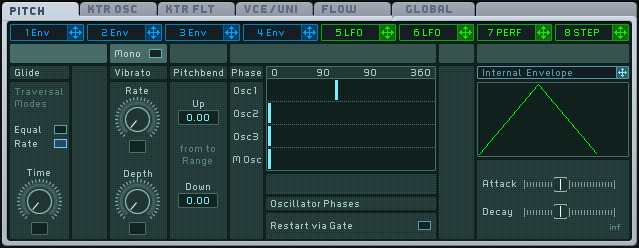
From left to right, we find several blocks of parameters labeled Glide, Vibrato, Pitchbend and Phase, respectively. Let’s look at these one at a time.
The Glide block of parameters controls the glide between sequentially played notes. Setting the glide controls allows smooth transitions between notes with different pitches. The block contains a switch and a knob:
The Glide mode switch allows you to select from two glide modes. In Equal Mode, all glides are equal in time, no matter how large the interval. In Rate Mode, the glide depends on the interval between the consecutive notes: if the two pitches are near each other, the glide will be shorter, and if the two pitches are further from each other, the glide will take longer.
The Time control adjusts the time needed by the glide function to go from the first note pitch to the following note pitch. When the knob is at full left, there is no glide at all, the pitch jumping all of a sudden to the next one. When you turn the knob to the right, the glide time increases and makes the transition between the notes smoother.
The Vibrato block controls the pitch oscillation around the base pitch of the played note:
The Rate control sets the speed of the oscillation.
The Depth control defines the amplitude of the oscillation.
At the top of this block, a Mono button forces the vibrato to be monophonic, i.e. the same oscillation is used to cause the vibrato for all played notes. In other words, when this button is activated, you will hear the pitch of all played notes oscillating together (in phase).
The Pitchbend block controls MASSIVE’s response to your master keyboard’s pitch bend wheel (or corresponding MIDI controller). In the Up and Down fields, you can set the upper and lower values for the pitch bend range when the pitch bend wheel is at full up or full down on your master keyboard, respectively. You can even set a Down value higher than the Up value here, thus inverting the action of your pitch bend wheel.
The Phase block controls the relative phase of MASSIVE’s three oscillators and modulation oscillator. At the block’s bottom, the Restart Via Gate button allows you to set each oscillator to restart at its original phase each time you hit a key. If this Button is activated, the phases are restarted with each new incoming note. (If the Button is deactivated, the phases are continuously played, and when you hit a key, the oscillators take the current phase as starting phase.) The Phase Graphic display shows four lines corresponding to the four oscillators in MASSIVE (the three main oscillators plus the modulation oscillator). The x-axis represents the phases. On each line, a Phase slider indicates the current phase for each oscillator. You can modify this phase by dragging the Phase Slider to the left or to the right.
The right part of the interface contains an innovative and powerful feature: an internal envelope that can directly modulate the Pitch parameters themselves. Note that you can use all available modulation sources, e.g. the Stepper, to modulate the OSC Page’s parameters; but you can also use this internal modulation source for basic tasks. For instance, the envelope can be used to slowly increase the vibrato depth, naturally fading in the vibrato after some time.
This envelope is depicted in the upper right part of the Pitch Page, on the Internal Envelope Graphic Display. Above, you see a header similar to the Modulation Pages tab headers, and a modulation handle next to it: You can use the handle like any other modulation handle, particularly to modulate the Glide Time control and the Vibrato Rate and Depth controls of this OSC Page.
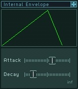
In the lower part of this block, you will find two parameters to control this envelope: the Attack fader adjusts the attack of the envelope, and the Decay Fader adjusts its decay. All adjustments are represented on the Internal Envelope display.
Keytracking Oscillator
The Keytracking Oscillator Page allows you to define the pitch response of the oscillators to the pitch of the incoming MIDI notes. On an acoustic keyboard instrument (let’s say a piano), the further to the left that you play a note, the lower the pitch of the sound. The further to the right you play on the keyboard, the higher the pitch. Thus, the pitch follows the position on the keyboard in a linear way. With the Keytracking Oscillator Page, you can alter this behavior for each of MASSIVE’s oscillators.
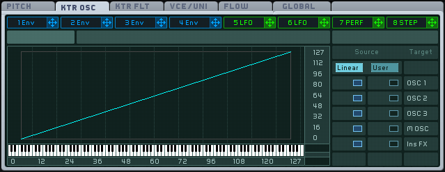
The Keytracking Oscillator page is divided into two parts: at the left, a Mapping Area shows how the current keytracking response is set up; on the right, a Mapping Selector allows you to map this keytracking response to the individual oscillators.
Two keytracking responses are available:
The Linear response is the usual keytracking response (with the lower pitches on the left and the higher ones on the right like an acoustic keyboard), represented by a simple line going from (0.0) to (127.127). This response cannot be edited.
The User response is freely assignable and you can tweak it according to your wishes.
You can choose to assign one or the other of these keytracking responses for each oscillator individually. This is done in the Mapping selector. This is basically a selection matrix. You can assign the Linear or User Response (represented by the two columns here) to one or several targets including the three main Oscillators, the Modulation Oscillator and the Insert Effects (as shown in the five rows here).
To assign a response to a specific target, click on the corresponding box in the matrix. For example, if you want to assign the User Response to Oscillator 3, click on the box in the column User and the row OSC 3 so that it is activated (you will see it turn blue). In this case, the other box in the same row is automatically deactivated (since only one or the other of them can be active at one time). If you click on the box again, it is deactivated. You can decide to deactivate both boxes on a row, removing all keytracking for this target. The outgoing pitch is then set to 64, no matter what the incoming pitch is.
The Mapping area graphically represents how the MIDI incoming pitch is interpreted to produce the outgoing pitch. The horizontal axis shows the incoming pitch, and the vertical axis shows the resulting outgoing pitch. At the bottom, a virtual keyboard represents the entire pitch range. The numbers on both axes are the MIDI note numbers, from 0 to 127. When you hit a key on your master keyboard, a vertical line appears on the Mapping Area showing the pitch of that incoming note.
Each time you click on a box in the Mapping Selector to activate or deactivate it, the Mapping Area displays the new keytracking response. If you click on a box in the User column, you will see a set of breakpoints appearing on the Mapping Area’s keytracking response line. You can edit this User Response in the Mapping Area by using these breakpoints.
You can move the three central breakpoints on both axis, and the first and last Breakpoints on the vertical axis, by simply clicking and dragging them with the mouse. You also have the following options to make your editing easier:
Alt-dragging a breakpoint forces it to move on the vertical axis only, allowing you to define an output pitch for a particular input pitch.
Shift-dragging a point allows you to make finer adjustments.
In this way you can define new response segments between each Breakpoint pair as in this image:
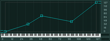
When you click on a Breakpoint, both the x- and y-axis display small lines pointing to their coordinates. The coordinate numerical values are also displayed in the two small fields at the right of the horizontal axis and at the bottom of the vertical axis.
If you double-click on a particular Breakpoint, you will delete the whole User Response and replace it by a horizontal line at the Breakpoint’s vertical level, thus creating a constant keytracking response at this particular outgoing pitch.
Keytracking Filter
The Keytracking Filter Page is very similar to the Keytracking Oscillator Page that we just described. It also deals with keytracking responses to incoming MIDI notes. However, it does not control the oscillators' outgoing pitch but rather affects the parameters of MASSIVE’s Filters.
This can be useful, for example, if you have low-pass filter shaping your sound: if the filter cutoff was constant, you would have louder sounds in the lower part of the key range, and softer (or even muted) sounds in its higher part, since only the low frequencies pass through the filter. By allowing the filter cutoff value to follow the incoming MIDI note pitch, the filter’s effect (how it modifies the sound) stays relevant for every incoming note.
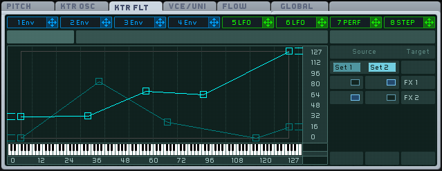
You will find the same basic layout structure here as in the Keytracking Oscillator Page: a Mapping Area on the left, and a Mapping Selector on the right. Please refer to the above section about the Keytracking Oscillator page for detailed information on how this Mapping system works. Here we will describe only how the Keytracking Filter Page differs from the Keytracking Oscillator Page.
In the first place, the Mapping selector here looks slightly different:
Instead of a Linear and a User Response, we find here two editable User responses, labeled Set 1 and Set 2.
The possible targets here are the two Filters, instead of the Oscillators.
Another difference you will notice is that this Mapping Area features two keytracking response lines, instead of only one. They allow you to control two different parameters of the corresponding filter. The light blue line refers to the Filter’s first parameter and the dark blue line refers to its second parameter.
For all filters except the Comb filter, these first and second parameters refer to the Cutoff and Resonance parameters, respectively. In the case of the Comb filter, the affected parameters are Pitch and Dampnening.
For all other controls and behaviors, please refer to the previous section about the Keytracking Oscillator Page.
Voicing
The Voicing Page allows you to control various parameters dealing with voices and polyphony. Note that section Signal Flow and Voicing explains voicing in more detail.
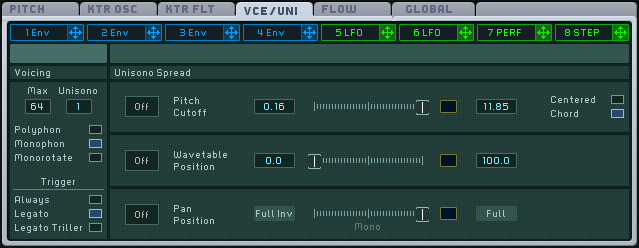
At left, the Voicing area allows you to define the polyphonic scheme that you want to use for MASSIVE. From top to bottom, we find the following controls.
The Voice Maximum control defines the maximal number of voices that can be played at the same time before the oldest is cut off. The range of this control is from 4 to 64. To modify this value, click on the number field and drag your mouse up or down, or double-click the field and enter the value via your computer keyboard. Be aware that each voice needs to be computed: the higher this value, the higher the CPU load shown in the navigation bar.
The Voice Maximum Control is generally known as polyphony, but this does not necessary imply that you can play as many notes at the same time as what is shown in this number field. This parameter controls the maximal number of voices, not the number of notes: if each pressed key triggers two voices, the maximal number of notes that you can play at the same time with your MIDI keyboard will actually be half of the maximal number of voices. Thus, the actual polyphony depends on the maximal number of voices and the number of voices triggered by each single note.
This is exactly what the Voice Unisono control does: it adjusts the number of voices that should be played for each key that is pressed on the keyboard. If the Voice Unisono Control is set to 1, only one voice is played when you hit a key; if it is set to a value higher than 1, then pressing a key will trigger as many voices as you have set. This control allows you to create thicker-sounding “stacked” sounds. Actually, though, if these unison voices were strictly identical, would not be of much musical interest. But MASSIVE allows you to modify the additional voices, and create some very interesting effects. This is called unisono spreading, and this is controlled by the Unisono Spread Area, which is explained further below.
Below these two number fields, we find the Mono/Poly switch. This switch lets you choose from three polyphonic modes:
Polyphonic allows you to play several notes at the same time, within the limits set by the Voice Maximum and Unisono controls.
Monophonic allows you to play only one note at a time. Note that the Monophonic mode deals with notes (i.e. pressed keys), not with voices. Thus, you can use this mode and still have many voices per note, as set by the Voice Unisono control. The next key you press will mute the previous one, with all its voices.
Monorotate is a special monophonic mode in which two notes are always played alternatively. If a new note is played while the previous one is still held, the old note will stop and the new one will start, just as in the normal monophonic mode described above. However, the old one will be faded out quickly to ensure that the abrupt stop of this note will not cause a click. This can be done as the new note is started on another layer of voices.
Below the Mono Poly switch is the Trigger switch. It defines how and whether the modulation sources are restarted from the beginning:
Always restarts the modulation sources each time a new MIDI note message is received.
Legato restarts the modulation sources whenever a new MIDI note message is received after the previously played note has been released; this means that the sources are not re-triggered if the notes are being played tied, slightly overlapping. This also implies that the previous note will be automatically stopped when the next note is played, even if the key has not been released on the keyboard yet.
Legato Trill restarts the modulation sources whenever a new MIDI note message is received and all other notes have been released before. This is convenient when playing trills or other ornaments on a keyboard: you only need to hit one of the trill notes while holding the other one constantly. This mode can be useful if you intend to hold one key all the time as a fundamental while playing figurations above it.
At the right of the Voice/Unisono page, Unisono Spread allows you to control how the different voices of a same note are differentiated from each other. You have three controls here: the Pitch and Cutoff, the Wavetable Position and the Panorama Position. Each control has a slider as in addition to one or more numeric displays and buttons.
Generally, for each of these parameters, the additional voices will sound more and more “distant” from the original voice. That is why this process is called “spreading”: the additional voices are “spread” out around the original one as you adjust the controls.
The parameters here are arranged in three rows. These rows share the same structure. From left to right, we find the following controls:
The Spread switch allows you to activate the corresponding parameter to spread the voices. If this switch is set to on (it will turn blue), then the voices will be spread out according to the controls in the respective section.
The Spread Amount control allows you to set the maximum amount of spreading between the different voices. Numerical fields allow you to set the spreading range. All active voices are spread out evenly within this maximum range. Thus, the more active voices you are using, the closer together each pair individual voices will be.
Here is some more information about the individual rows.
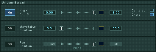
The range of the Pitch/Cutoff Spread Amount control is set in semitones and cents (hundredths of cents). The numerical values here can go from -12.00 semitones to +12.00 semitones. At the right of this slider, a Detune Mode switch allows you to choose from two detune modes:
Centered: The pitches are symmetrically spread around the main pitch. This is particularly useful with slight spreading values, up to about one semitone, which are often used to thicken a sound.
Chord: The pitches are spread alternatively below and above the main pitch. Use this mode with high spreading values that establish chord-like structures.
Here are two examples to understand how this works:

With the settings as above, the four active voices will be tuned according to the following list:
Voice 1: -75 cents
Voice 2: -25 cents
Voice 3: +25 cents
Voice 4: +75 cents
As you will notice, the original pitch is not present within this mode; rather, the four different voices surround it symmetrically. As the voices will be heard to merge into one, chorus-like sound with only one pitch, the original pitch will be heard nonetheless, as the center of the voice tunings.

With these settings, the voices will be tuned like this:
Voice 1: 0 (original pitch)
Voice 2: +12 semitones
Voice 3: -12 semitones
Voice 4: +24 semitones
Here, the original pitch is present (first voice), and the other voices are grouped around it, alternating between pitches below the main pitch (third voice) and above (second and fourth voice).
Below the Pitch/Cutoff Spread Amount control you will see the Wavetable Position Spread Amount control The range of this control is set as a percentage. This control will cause the Wavetable Position (adjusted by the WT-position knob) of the various voices to spread out around the original voice.
The Panorama Position Spread Amount control range is not editable. Rather, it allows you to adjust the stereo imaging of the voices. With the slider at far right, you will hear the full stereo image. When it is in the middle, you will hear a centered mono signal, and at far left, you will hear an inverted stereo image, with left and right signals reversed.
Routing
As you can see in the image below, the Routing Page shows you a graphic representation of the signal flow in MASSIVE:
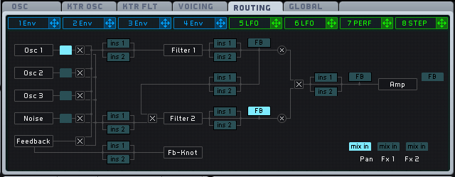
Here you can see the various modules and Sections in MASSIVE and how the signal flows between them. You can also see a number of buttons that can be activated or deactivated by clicking them. Activated buttons show up light blue here, deactivated buttons in a darker color.
The signal flow in MASSIVE is explained in detail in section Signal Flow and Voicing on Signal Flow and Voicing, please refer to this section for a full explanation of how this works. However, you should understand the function of the various buttons present here.
Looking to the left edge of the Routing Page, we see the three oscillators, labeled OSC1, Osc2 and Osc3. Under these is the Noise generator. Now, just to the right of each of these, you can see a small button that can be highlighted by clicking it. (Notice that only one of these buttons can be active at a time.) These are the Bypass Source selectors for each sound source. By clicking these in turn, you can select which audio signal will be passed directly to the Bypass Section (see section Bypass Section) towards the end of the signal chain.
There are also three Bypass Target selector buttons at the lower right of the Routing Page. Choosing one of these allows you to select the point at which the signal from the Bypass Section will be mixed back into the main signal: after the Pan, or after FX1 or FX2 in the Master Effects Section.
Looking just a bit further to the right of the Bypass Source Selectors, we see another column of six buttons marked alternately ins1, ins2, ins1, ins2 and so on. If we look around a bit more, we can see that there are a number of other similarly-labeled buttons placed elsewhere on the Routing Page. These are the Insert Effects Position selectors. You can use these to set the position of the Insert Effects (see section Insert Effects) in the signal chain. Setting the position of these effects can make a big difference in how they modify the sound. Note that you can only have one ins1 and one ins2 button selected at one time.
There are also a number of buttons here labelled FB. These are the Feedback Source selector buttons. Only one of these can be selected, and it determines the point at which part of the signal is routed back to the Feedback Section, where it can be reintroduced to the signal chain at the beginning. Note that you can apply one of the insert effects directly to the feedback signal.
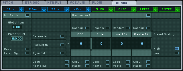
Global
The Global Page contains various parameters that are relevant for all other parts of MASSIVE, for instance the global tuning. This page also provides some copy and paste functionality as well as the ability to randomize the current sound’s settings.
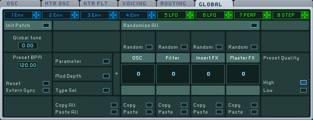
The Global tune parameter allows you to adjust MASSIVE’s tuning in semitones and cents.
The Preset BPM parameter sets the tempo of the internal clock in beats (quarter notes) per minute. This parameter is saved with the sound, used for example when the Stepper modulator is used in sync mode. The Preset BPM parameter is not relevant if External Sync is active.
Clicking on the Reset button resets the internal clock’s song position pointer to zero, like going to a track’s start in a sequencer. This is used to ensure the reproducibility of modulation source signal. This parameter is not relevant if External Sync is active.
If the External Sync is on, the internal clock is deactivated and clock is taken from MIDI signals arriving at the synthesizer. This is particularly useful when MASSIVE is used as a plug-in, as the host will provide a global clock signal for all plug-ins to synchronize them.
The Preset Quality buttons switch between two quality modes. High (using oversampling) should be used whenever possible, but note that the CPU load is increased with this setting.
Copy/Paste and Randomization can be applied module-wise in this section. There are four module groups: oscillators, filters, insert effects and master effects, arranged horizontally. For each group, you can select (vertically) whether the copy/paste/random function is applied to the parameter values, the modulation depths, or the type selection (e.g. wavetable selection). Thus you can specify the target of the operation in this table-like structure. Pressing the Random button randomizes the adjusted part of MASSIVE, e.g. the oscillators’ parameters. The amount of randomization is adjusted in percentages in the central boxes. A value of 25, for instance, changes the target values by a maximum of 25 percent around the actual value. These can be used to slightly modify settings (low values) or create completely new sounds (high values). The Copy function here writes the selected target into an internal buffer, and Paste writes the internal buffer onto the selected target. These functions can be used to copy parts of a sound (e.g. the filter settings) into another sound by copying the filter data into the internal buffer, loading another sound, and pasting the buffer again. This overwrites the current settings without asking.
Modulation Pages
Each of the eight Modulation Pages defines a modulation source that can be used to modulate MASSIVE’s other parameters. (For more information and step-by-step instructions on how exactly to assign modulation sources to destinations in MASSIVE, see section Modulation Controls.)
The modulation sources are grouped into two basic types, the Envelopes (tabs 1-4, color-coded blue) and the Assignable Pages (tabs 5-8, color-coded green). Each of the four Assignable Pages allows you to choose between three specific modulation source types: LFO, Stepper and Performer. To choose one of these types, use the dropdown menu in the upper-right corner of the individual modulation page.
Structure
All of the Modulation Pages share the same basic structure:
The tab header displays the modulation source number and type. Click on it to select a specific modulation page and display its parameters. When a modulation source is selected, its tab header is will be highlighted as in the image below:

The modulation handle (the little cross at the right of each tab header) allows you to assign this modulation source to the desired destination parameter(s), as described above.
Note
It is not necessary to select a modulation source first before assigning it. Even if a modulation source is not selected (and its parameters not displayed), you can still make an assignment between its modulation handle and a destination modulation slot, allowing you to quickly make a number of different assignments without having to flip back and forth between the individual modulation pages here.
The top row of each modulation page includes general options for that particular modulation source.

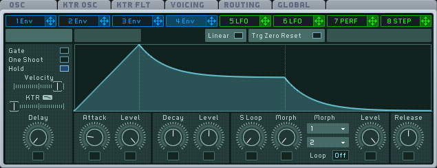
Envelopes
The first four Modulation Pages starting from the left allow you to define four individual modulation envelopes. Their tab headers are blue.
These envelopes are designed according to the ADSR (Attack-Decay-Sustain-Release) scheme, with certain special features related to the sustain stage and for trigger options.
The envelope shape is represented on the Graphic Display:
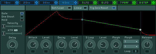
The knobs below the Graphic Display are used to edit the envelope. Try moving them and you will see exactly how each of them influences the envelope shape. The Graphic Display always shows you the current shape of the envelope, as determined by how you set the knobs and menus.
The top row for the envelope includes two buttons:
The Linear Transition switch switches the Decay shape from logarithmic to linear. By default, the Attack shape of the envelope is linear, while the Decay and Release shapes are logarithmic. With this Switch activated, the Decay shape becomes linear as well.
The Trigger Mode switch causes the envelope to retrigger from the beginning every time it receives an incoming MIDI note. If this is disabled, the envelope will not start at zero if the previous note’s release period is not over yet; instead using the current level as its starting point.
At the far left of the Envelope Page, you will find another set of global controls that modify the envelope response to incoming MIDI notes.
At the top left, the Play Mode selector allows you to choose from three Play Modes: Gate, One Shoot and Hold (see below).

This Play mode determines how the envelope will be read:
With Gate selected, when you press a key, the envelope is started and read until its end. However, if you release the key before the envelope comes to the end, it will immediately jump to the Release stage.
With One Shoot selected, as soon as a key is pressed, the envelope is read to the end, even if the key is released sooner. The full sustain stage (with any possible loops, see below for more on this) is also read.
With Hold selected, as soon as a key is pressed, the envelope is read until the Sustain end point (including possible loops). It remains there also if the triggering key is released. The envelope jumps to the release stage only when the triggering key is pressed a second time, or if another key is pressed, triggering another note. However, if another key is pressed while the initial key is still held, the new note will be stacked onto the initial one, building a chord. All chord notes jump to the release stage simultaneously when all keys have been released and a new key is pressed. This mode can be particularly useful in live situations when MASSIVE is being used to generate grooves or rhythmic soundscapes.
Just below the Play Mode Selector, two faders allow you to adjust the influence of incoming MIDI notes on the overall envelope amplitude:
The Velocity Sensitivity fader controls the influence of the incoming MIDI note’s velocity on the overall envelope amplitude. If the Fader is at full left, the envelope amplitude is not influenced at all by the incoming note’s velocity. If the Fader is at full right, the overall envelope amplitude is directly proportional to the incoming note’s velocity.
The Keytracking fader controls the influence of the incoming note’s pitch on the overall envelope amplitude as follows: the higher the pitch, the smaller the envelope amplitude. If the Fader is at full left, the envelope amplitude is not influenced at all by the MIDI pitch. If you move the Fader to the right, the overall envelope amplitude is more and more influenced by the incoming note’s pitch, with higher sounds becoming lower in volume.
At the bottom of this area, the Delay Time control allows you to insert a delay between the time when you hit the key and the time when the envelope starts.
Let’s look now at the parameters for each envelope stage.
The Attack stage starts from zero (no sound) and goes up until it reaches the maximum value you have set. Two controls allow you to define how the envelope reaches the maximum attack value:
The Attack control adjusts the time needed by the envelope to go from zero to the first maximum point. If you turn the knob clockwise, the attack becomes longer, and your sound will start more smoothly.
Next to this, the Level control sets the amplitude of the maximum point. It can be effective in many cases to give this parameter a higher value than the following Decay Level; this will give some initial punch to your sound when you hit a key.
The Decay stage goes from Attack's maximum value and leads to the Sustain stage. Again, two controls provide control over the time and level domains:
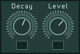
The Decay control adjusts the time needed by the envelope to go from the attack’s maximum value to the decay end point.
The following Level control sets the amplitude of this final point, thus also adjusting the value for the sustain starting point.
The Sustain stage provides two special features. First, a loop function allows you to play this part of the envelope back and forth a set number of times. You can think of this as a kind of mini-LFO inside the envelope, looping only a certain fixed number of times between the Decay and Release stages before moving on. Second, a morphing function provides you with two selectable sustain shapes, allowing you to morph the actual sustain shape between these two.
The controls for the Sustain stage are as follows, from left to right:
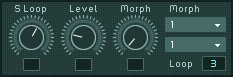
The S Loop control adjusts the time between the sustain start and end points. If you turn it clockwise, you increase the sustain duration, and therefore also lower the speed of the envelope in the sustain stage.
The Level control sets the amplitude of the sustain end point.
The Morph control adjusts the actual sustain shape between the two reference sustain shapes defined by the Sustain Morph Popup Menus (see below). If the knob is turned full left, the sustain shape will be the shape selected in the first Morph Menu. With the knob at full right, the shape will fit the one selected in the second Morph Menu. In between, the actual sustain shape will be an interpolation between the two selected shapes. The Graphic Display indicates the actual interpolated curve as you change the morph settings.
The first Morph drop-down menu allows you to select the first boundary for the morphing function.
The second Morph drop-down menu allows you to select the other boundary for the morphing function. If you choose the same shape as in the other menu, the morphing function will be deactivated (as it will have no effect to morph between two shapes that are exactly the same anyway).
The Loop count at the lower right of the Sustain stage defines how many times the Sustain stage will loop. Actually, the envelope executes a back and forth movement, and via the Sustain Loop Count you define the number of times it will play forward and backward. If you select 0, the Sustain stage is ignored; depending on the Play Mode Selector setting (see above), the envelope will then go directly to the Release stage, or stay at the sustain start point level as long as you hold the key, or stay at this level as long as you hold the key or no other note comes. If you select 1, the envelope goes once through the sustain stage, from left to right, then to the Release stage. If you select 2, the envelope will go from the start point to the end point, and back to the start point, and then it will jump to the Release stage. And so on. You can turn this up to a maximum of 32 half-cycles (i.e. 16 times forwards and 16 backwards). However, the menu also allows you to select an infinite loop (choose inf in the menu, all the way to the top of the popup menu.), which makes the sustain stage loop forever.
Note: A white dot in the Graphic Display indicates where the cycle process will stop. An odd number setting for the Sustain Loop Count will cause the envelope to stop on the right side of the sustain stage, at the sustain level. An even number lets the sustain cycle stop on the left side of the sustain stage, therefore at the decay level.
The Release stage defines how the envelope ends up. You only have one control for this stage, called Release control, adjusting the time for the envelope to fade to zero.

This envelope structure is very versatile, yet you can also use it for classic ADSR envelopes: just set the Sustain Loop Count to off, then turn the Attack Level to its maximum, and adjust the Attack and Decay Time Controls to medium values. Now you can use the Decay Level Control as a Sustain Level control.
Common Controls for LFO, Stepper and Performer
The last four Modulation Pages allows you to define four other modulation sources; in each of these, you can choose from three different modes: LFO, Stepper and Performer. Their tab headers are green.
Click on one of the four green tab headers to select the corresponding modulation source and display its Modulation Page with all its parameters visible.
Most of the controls in the top row of these three modulation modes are the same, so let’s have a look at them from left to right:
The Mono button, when activated, will force the modulator to output a monophonic modulation signal, no matter how many voices are played. You can use this function to “synchronize” the modulations of different voices.
The Moder drop-down menu, at the far right, allows you to select the kind of modulation source you want to use in this Modulation Page (LFO, Stepper or Performer).
These three modulation modes also share the same left block of controls:

From top to bottom, we find:
The Rate control and its associated Sync switch. The Rate Control adjusts the speed of the modulation source. When the Sync Switch is engaged, the modulation source is synchronized with the master clock or external sync (see the Global Page). The Rate Control then becomes a Ratio Control with two number fields, allowing you to specify the duration of one step of the modulation source. For LFOs this is one complete cycle; for all other sources this is actually one step within the sequence. The lower value determines the temporal unit; e.g. a 16 represents a sixteenth note, and 4 represents a quarter note (one beat). The upper value determines the actual length of the cycle as multiples of the lower unit, e.g. setting a pair of 3 (upper value) and 16 (lower value) will cause the Stepper to proceed to the next step after three sixteenth notes have passed according to the global clock (see the Global Page in section General Pages).


The Restart switch causes the envelope to re-trigger every time it receives a note (i.e., the envelope starts from the same point each time). If the Restart Switch is deactivated, the modulation source runs in the background: when you play a note, it is driven by the modulator, starting at the current modulator position.
The Amplification control sets the modulation signal amplitude. Its effect is similar to the modulation amount setting (set by clicking on the assigned modulation slot under the target knob and dragging the mouse up or down, see Modulation Controls on setting modulation assignments for more on this). The difference is that if you modulate different targets with this modulation source, this Amplification Control has an effect on all of the targets. Note that your modulation assignments may have no audible effect if this Amplification Control is set to full left, as this is equivalent to no effect!
All the other controls in these pages are specific to the particular modulation source mode you have chosen, even if there are some similarities between them.
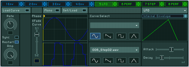
LFO
LFO stands for Low Frequency Oscillator. This modulator generates a periodic signal at a low frequency. The word “low” here means that its frequency is lower than those which a human ear interprets as “sound”: The LFO does not directly add anything to the audio content, but instead it can be used to continuously modify the sound’s parameters.
For the controls included in the top row and in the left block, please refer to the previous section (“Common Controls for LFO, Stepper and Performer”).
We will describe here the controls that are specific to the LFO modulation source.
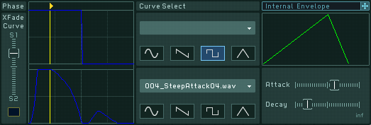
Note that each LFO in MASSIVE is actually a double LFO: the modulation source features a morphing function that allows you to interpolate between two curves (similarly to the sustain stage of the envelope modulation source described above). You can adjust the LFO curve on the fly by moving the Xfade Curve slider. This is all done in the left part of the interface.
The two curves are represented in the upper and lower part. For each of the two curves, the interface provides you with:
The Curve Graphic display representing the curve’s shape
The Quick Curve Morph selector, allowing you to select a shape among four basic LFO waveforms (sine, sawtooth, square and triangle),
The Curve Morph drop-down menu, giving you access to more complex waveforms to choose from.
At far left, the Curve Morph control fader allows you to adjust the interpolation between both curves, which will be the effective played LFO curve. With the fader at full top, you select only the upper curve. With the fader at full bottom, you select the lower curve. In between, you can adjust the interpolation of both.
Above the Curve Morph Fader and the Curve Graphic Displays, the Phase fader sets the starting phase of the curves. In other words, you can choose if you want to start the square LFO at the upper stage or the lower stage.
The phase position is represented on the Phase Fader by a small yellow triangle and on the Curve Graphic Displays by a yellow vertical line that indicates where exactly the LFO signal will start.
The right part of the interface contains a useful feature already seen in the OSC Page: an internal envelope that can modulate the LFO parameters themselves. This envelope is depicted in the upper right part of the Modulation Page, on the Internal Envelope Graphic display. Above, you can see a header similar to the Modulation Pages tab headers, and a small modulation handle next to it from which you can make modulation assignments to the three internal targets: the Rate control (only possible if the Sync switch is deactivated), the Amplification Control and the Curve Morph control.
In the lower part, you will find two parameters for this envelope: the Attack fader adjusts the attack of the envelope, and the Decay fader adjusts its decay. All adjustments are represented on the Internal Envelope Graphic display.
Stepper
The Stepper is basically a step sequencer. It allows you to define a certain number of steps, each of them having a specific amplitude value. The steps are read in a looped sequence, recreating a periodic signal to be used as a modulation.
For the controls included in the top row and in the left block, please refer to the section Common Controls for LFO, Stepper and Performer.
We will describe here the controls specific to the Stepper modulation source.
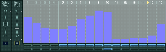
The main part of the Stepper Modulation Page is occupied by the Stepper Graphic display, showing the different steps. For each step, the corresponding amplitude is represented by a bar. To adjust each amplitude, click on the bar and drag the mouse up or down. Hold the keyboard’s Shift key for fine adjustments.
On the top of the Display, a Loop Area Bar shows the step numbers. On this bar, a yellow triangle indicates the current step being played. The triangle moves through all steps included in the loop.
The steps included in the loop have their numbers highlighted in the Loop Area Bar.
To edit the loop range, click on the first or last step number in the loop, hold the mouse button and drag it to the left or to the right: the highlighted numbers follow the mouse movements, defining a new loop range. The loop speed is controlled by the Rate/Ratio control, in the left block of controls described earlier (in the section Common Controls for LFO, Stepper and Performer.)
At the left of the Stepper Graphic display, there are two faders:
The Glide Mod fader adjusts the glide between the former step and the current step. The glide can be used to create soft transitions between steps. When this is turned all the way down, there is no glide between the steps; when turned up to the top, the glide is at its maximum. Note that this functionality has to be activated for each step individually with the Step Activation Rows explained below.
The Amp Mod fader adjusts the overall amplitude of the modulation defined by the step sequences. When all the way down, there is no modulation (whatever the bars are); when all the way up, the modulation is at its maximum. Note that this functionality has to be activated for each step individually with the Step Activation Rows explained below.
These two faders can be modulated, as indicated by the small black modulation slot under each of them. The modulation amount is then shown on their right side by a vertical bar, with the color of the modulation source, like all other modulatable parameters.
Each of these faders is related to one of the two Step Activation rows below the display. Each Step Activation row contains a sequence of boxes, one under each step. Each box defines if the corresponding step will be affected by the relevant fader or not. If a box is activated (blue), the corresponding step will follow the fader control. If it’s deactivated (black), the step is not affected by the fader setting. To activate a box, click on it. You also can hold the mouse button and drag the mouse to activate or deactivate several boxes.
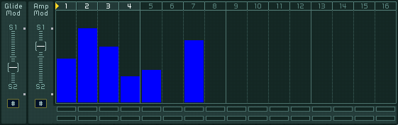
For example, in the image above, we can see that:
The loop includes the steps 5 to 16.
The Glide Modulation Control is at a middle setting, and it is modulated by Macro Control 5.
Only step 10 is affected by this glide modulation (as shown by the lower Step Activation Row).
The Amplitude Modulation Control is at a low setting, and it is modulated by the Macro Control 3.
All the steps in the loop are affected by this amplitude modulation (as shown by the upper Step Activation Row).
Performer
The Performer is quite similar to the Stepper in its implementation, but it allows you to create much more complex sequences. The Performer lets you generate step-sequenced rhythms with the aid of waveforms instead of simple vertical bars.
Furthermore, it also features a morph function that allows you to interpolate between two sequences, just as in the envelope and in the LFO modulation sources (see above).
For the controls included in the top row and in the left block, please refer to the section Common Controls for LFO, Stepper and Performer.
We will describe here the controls specific to the Performer modulation source.
The steps are depicted in the Performer Graphic display. Each step displays its loaded waveform.
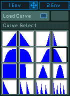
You can choose a specific waveform for each step. To choose a waveform, click on the Load Curve button at the top left of the Modulation Page. This will open a matrix with a number of different waveforms. Here you can select and assign various waveforms to the steps: select one waveform (by clicking), then click on the target step frame. You can do multiple assignments (one waveform to several steps) by holding the Shift key and clicking on the desired steps.
Like in the Stepper, you can adjust each step’s amplitude by clicking and holding its waveform and dragging the mouse up or down. Hold the keyboard’s Shift key for fine adjustments.
When you are done with the waveform assignments, click again on the Load Curve button to close the matrix.
As in the Stepper, a Loop Area Bar on the top of the Performer Graphic Display shows the step numbers. It also displays a yellow triangle that indicates the current step being played. The triangle moves through all steps included in the loop.
The steps included in the loop have their numbers highlighted in the Loop Area Bar.
To edit the loop range, click on the first or last step number in the loop, hold the mouse button and drag it to the left or to the right: the highlighted numbers follow the mouse movements, defining a new loop range. The loop speed is controlled by the Rate/Ratio control, in the left block of controls described earlier (refer to Common Controls for LFO, Stepper and Performer.)
At the left of the Performer Graphic Display, we find two faders:
The Amp Mod fader adjusts the overall amplitude of the modulation defined by the step sequences. At full down, there is no modulation (whatever the waveforms are); at full up, the modulation is at its maximum. Note that this functionality has to be activated for each step individually with the Step Activation Rows explained below.
The Seq fader adjusts the interpolation between both sequences, i.e. the sequence effectively played by the Performer. At full down, only the lower sequence is played; at full up, only the upper sequence is played. In between, you can adjust the interpolation. Note that this functionality has to be activated for each step individually with the Step Activation Rows explained below.
The two faders can be modulated, as indicated by the small black box under each of them. The modulation amount is then shown on their right side by a vertical bar, with the color of the modulation source, like all other parameters that can be modulated.
Each of these faders is related to one of the two Step Activation Rows below the Display. Each Step Activation Row contains a sequence of boxes, one under each step. Each box defines if the corresponding step will be affected by the relevant fader or not. If a box is activated (blue), the corresponding step will follow the fader control. If it’s deactivated (black), the step is not affected by the fader setting. You can also hold the mouse button and drag the mouse to activate/deactivate several boxes.
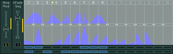
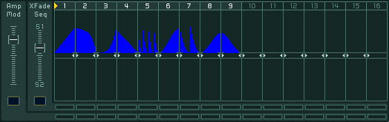
For example, on the picture above, we see that:
The loop includes the first 9 steps.
The Amplitude Modulation Control is at a quite low setting, and it is modulated by Macro Control 1.
Only the steps 1, 3, 5-9 are affected by this amplitude modulation (as shown by the lower Step Activation Row).
The Sequence Morph Control is at a quite high setting, and it is modulated (in the opposite direction) by the Macro Control 2.
Only the steps 1, 2, 7-9 are affected by this sequence morphing (as shown by the upper Step Activation Row).