Modulation Pane
The Modulation pane provides modulation sources including LFOs, Shapers, and a Matrix for adding movement, altering and combining modulation sources.
The Modulation pane is where the ASHLIGHT comes to life, hosting the modulation sources that bring movement and dynamics to your sound. The Modulation pane contains two LFO, two Shapers, and a Matrix for altering and combining modulation sources. The powerful routing Matrix encourages interesting modulation combinations that inspire creativity and foster unique sonic results. In this section, you can create elaborate modulation sources tailored to your Sample and Grain layers. Use the Matrix section to combine multiple modulators, for example, an LFO and a Macro control, to create a complex chain of modulators that allow for intricate shaping and manipulation. Due to the option of modulator chaining, all modulators are unipolar.
The modulation direction can be simply swapped by holding [Option] (mac) / [Alt] (Windows) + [Shift] whilst clicking on each knob. Hold down [Option] / [Alt] on a Modulation knob to adjust the knob value and the modulation range simultaneously. The signal of the individual voices is mixed down to one stereo stream at the output of the corresponding layer engine before the FX chain is entered. Polyphonic modulation is only possible before the mixdown.
Modulation Pane Overview
The Modulation pane contains the following elements and controls:
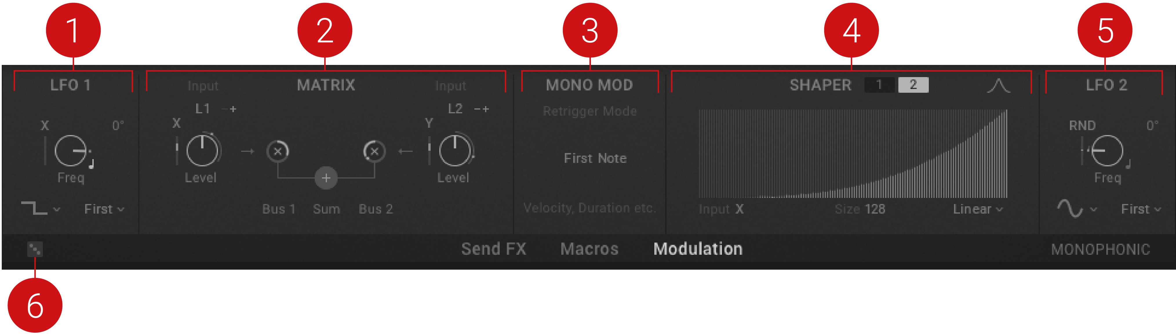
LFO 1: A modulation source that can be assigned to adjust various parameters. For more information, refer to LFO 1.
MATRIX: Contains two Buses, which can either work in attenuation or summing mode. For more information, refer to Matrix.
Mono Modulation Trigger: Selects which note should trigger the monophonic modulation path used for effects modulation. First Note’ is the default and most useful setting. Highest or Lowest enables the modulator to restart whenever the corresponding note changes.
SHAPER: A Shaper is used to define a new output value for every input value. For more information, refer to Shaper.
LFO 2: A modulation source that can be assigned to adjust various parameters. For more information, refer to LFO 2
Randomize: Produces random values for all parameters in the Modulation pane.
LFO 1
The Modulation pane provides two LFOs that can be assigned to modulate parameters of the ASHLIGHT. Combining different LFOs in the Bus Matrix can create complex modulation sources that unfold slowly over time. Eight different waveforms provide options for intricate modulation effects, and five Trigger modes determine the behavior of the LFO.
The LFO contains the following parameters:
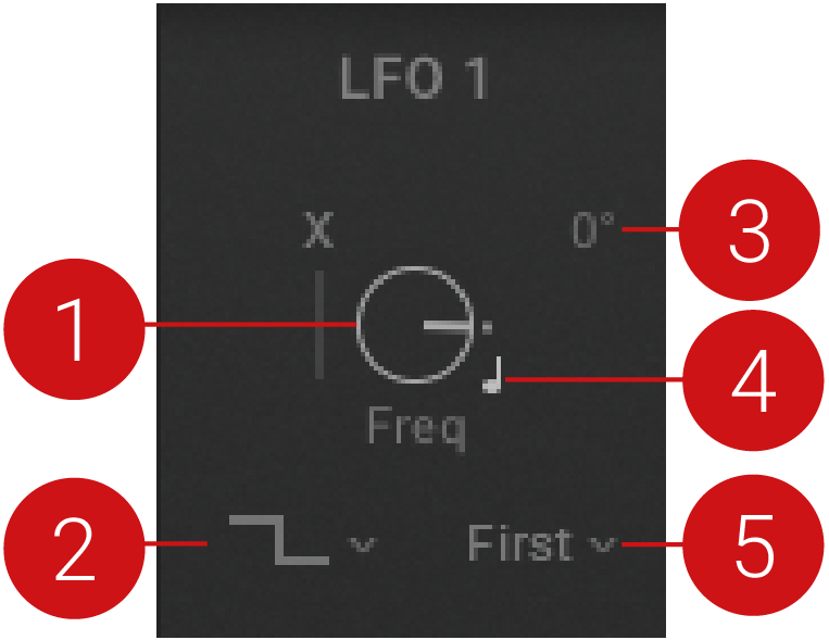 |
Freq: Sets the oscillation frequency of the LFO. This parameter can be synchronized to the master clock.
Waveform Type: Selects one of eight waveform types (Sine, Triangle, Square, Ramp up, Ramp down, Random, Seek 1 and Seek 2). Seek 1 and Seek 2 provide smooth, random LFOs.
LFO Phase: Sets the starting point for the LFO in degrees, ranging from 0 - 360. This setting has no affect when the LFO is in Free mode, or when Random, Seek 1, or Seek 2 waveforms are selected.
Sync (crotchet icon): Determines if the LFO speed is set in Hertz or in relation to the master clock as a musical duration. When the icon is lit, the LFO speed is set as divisions of musical timing, which are displayed when the Freq control is adjusted.
Trigger Mode: Selects one of five modes (Free, First, Retrig, Once, 1st 1x), which determines the retrigger behavior of the LFO. Free mode provides polyphonic modulation with a random start phase. First mode restarts the LFO with the first note only. In Retrig mode, the LFO restarts for each key pressed. Once mode triggers only one LFO cycle. 1st 1x triggers one LFO cycle for the first note only. In all modes, excluding Free, the Start phase setting is taken into account.
Matrix
The Matrix section is where you can combine sources to create more complex modulators. The Matrix contains two Buses, which can either work in Attenuation or Summing mode. Each Bus features two inputs which are processed and sent to the modulation targets Bus 1 and Bus 2. These two Buses can then be individually sent to any assignable parameter. The Matrix input signals can be converted into a bipolar modulation source. In Attenuation mode, as indicated by an x, the attenuator works as a multiplicator. In Summing mode, as indicated by a +, the two modulation sources are added together. Each Bus can be assigned to a different mode and there is also the Sum of both busses available as a modulation source. You can monitor the result of each Matrix output with level indicators.
Attenuation Mode
The following controls are available in Attenuation mode. Controls are the same for Bus 2.
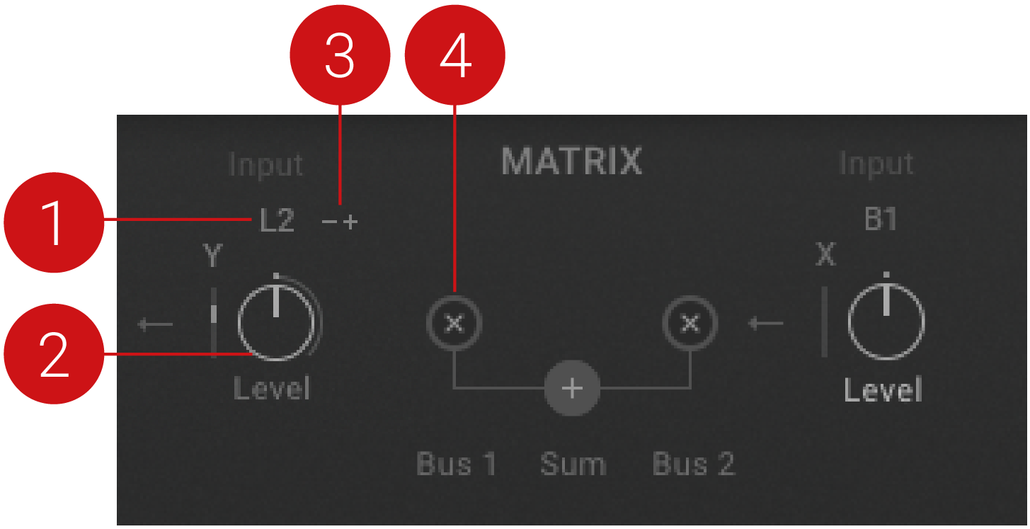 |
Modulation Source: Selects the modulation source applied to this parameter. Note that some modulations, for example the Grain parameters, are polyphonic and others are monophonic.
Bus 1 Level: Determines if the input value is decreased, amplified or optionally inverted. The result is available as Bus 1 in the Modulation source menu. The range spans from -200% to 200%.
Input Mode: Defines the range of the incoming modulation signal. The values range from 0 to 1 or from -1 to 1. The latter is particularly useful for bipolar pitch modulation.
Bus 1 Mode: Determines whether the corresponding Matrix Bus works as a modulatable attenuverter/multiplicator or as a simple modulation source mixer which adds the two modulation signals together.
Summing Mode
The following controls are available in Summing mode. Controls are the same for Bus 2.
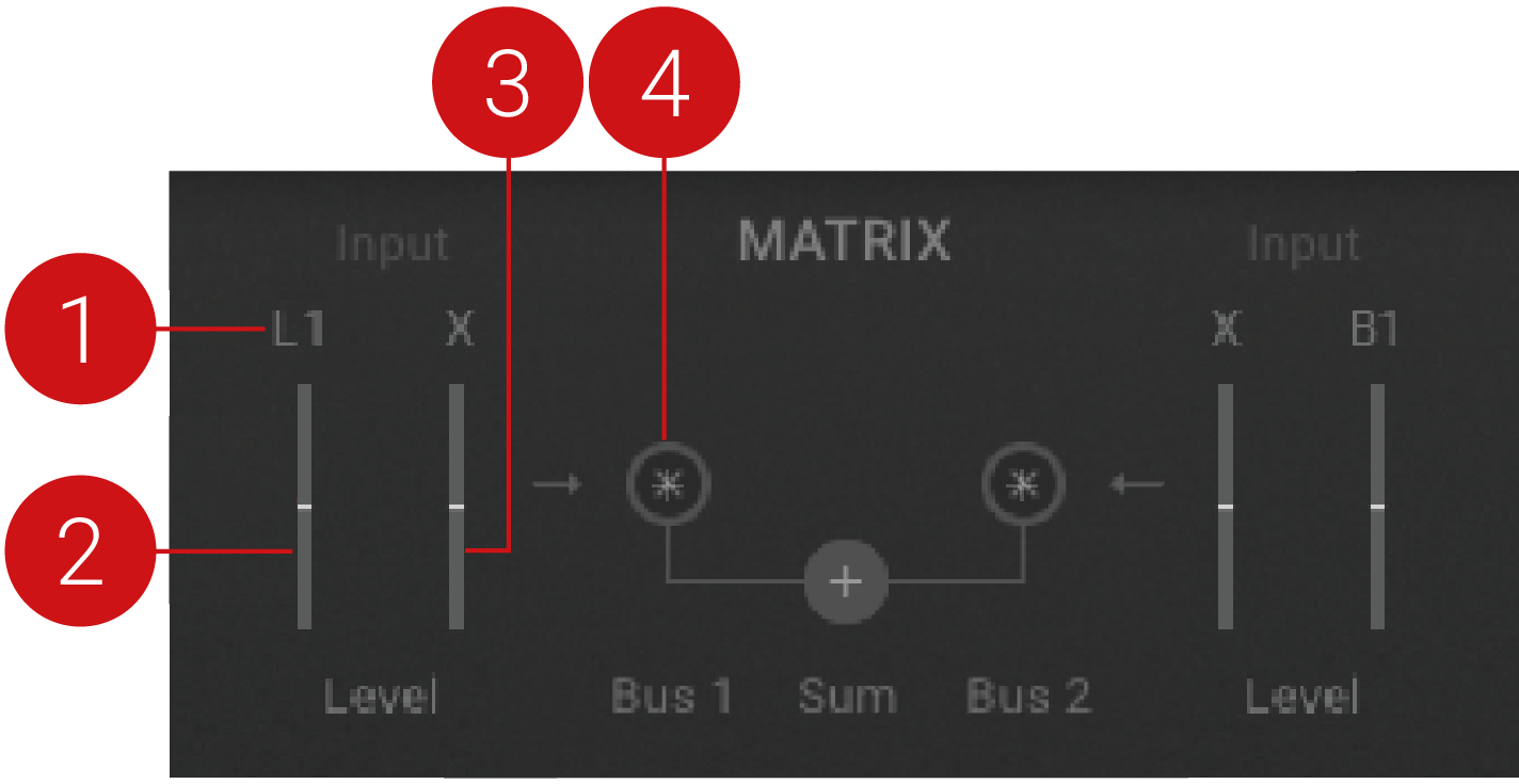 |
Modulation Source: Selects the modulation source applied to this parameter. Note that some modulations, for example, the Grain parameters, are polyphonic and others are monophonic.
Bus 1 Mix 1: Determines if the input modulation value is decreased or optionally inverted and subsequently summed to Matrix Bus 1. The range comprises -100% to 100%.
Bus 1 Mix 2: Determines if the input modulation value is decreased or optionally inverted and subsequently summed to Matrix Bus 1. The range comprises -100% to 100%.
Bus 1 Mode: Determines whether the corresponding Matrix Bus works as a modulatable attenuverter/multiplicator or as a simple modulation source mixer which adds the two modulation signals together.
Shaper
The Modulation pane provides two Shapers that can be used to define a new output value for every input value. By using an LFO as the input of the Shaper and painting in the desired curve, you can generate many different types of waveforms. This enables you to create more interesting and elaborate modulation sources, that can achieve targeted results. The Shaper also offers different options of interpolation, which allows for smooth transition from one step to the next.
The position of the cursor per voice is available as a modulation source for the inputs of the Shapers. This is accessed by selecting POS Cursor Position from the Input Source menu. This allows you to define a value for all positions in the sample. For example, lowering the volume or pitch whenever the cursor scans over a certain position.
The Shapers contain the following parameters:
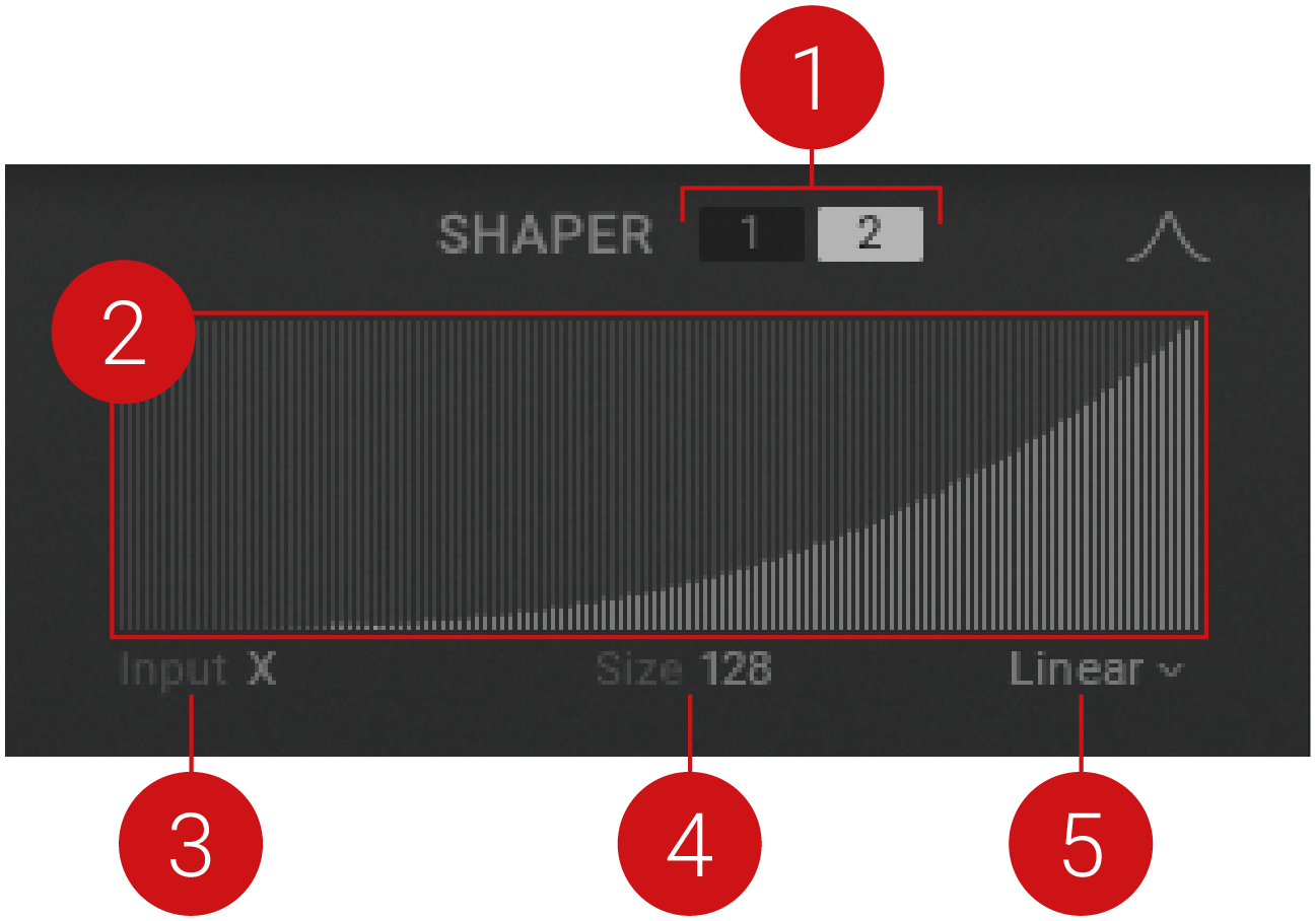 |
Shaper 1/2: Toggles between the two available Shapers.
Shaper display: Displays a visual representation of the current state of the Shaper.
Input Source: Selects the modulation source that is applied to the Shaper.
Size: Determines how many steps the Shaper provides. The maximum number of steps is 128.
Interpolation Mode: Determines how the Shaper interpolates when transitioning from one step to the next. This also features randomization and smoothing functions.
Random: Fills the visible shaper range with random numbers
Smooth: Removes edges from the curve whilst leaving the start and end values untouched. Click to smooth the currently visible curve. Apply the smoothing as often as necessary to achieve the desired curve.
Smooth Wrap: Removes edges from the curve while generating a smooth transition between the end and start value.
LFO 2
The second LFO provided in the Modulation pane can be assigned to modulate parameters of the ASHLIGHT . Eight different waveforms provide options for varied modulation effects, and five Trigger modes offer further control over the behavior of the LFO. Use the Bus Matrix to combine multiple LFOs and create elaborate modulation sources that evolve unexpectedly over an extended period of time.
The LFO contains the following parameters:
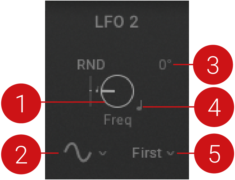 |
Freq: Sets the oscillation frequency of the LFO. This parameter can by synchronized to the master clock.
Waveform Type: Selects one of eight waveform types (Sine, Triangle, Square, Ramp up, Ramp down, Random, Seek 1 and Seek 2). Seek 1 and Seek 2 provide smooth, random LFOs.
LFO Phase: Sets the starting point for the LFO in degrees, ranging from 0 - 360. This setting has no affect when the LFO is in Free mode, or when Random, Seek 1, or Seek 2 waveforms are selected.
Sync (crotchet icon): Determines if the LFO speed is set in Hertz or in relation to the master clock as a musical duration. When the icon is lit, the LFO speed is set as divisions of musical timing, which are displayed when the Freq control is adjusted.
Trigger Mode: Selects one of five modes (Free, First, Retrig, Once, 1st 1x), which determines the retrigger behavior of the LFO. Free mode provides polyphonic modulation with a random start phase. First mode restarts the LFO with the first note only. In Retrig mode, the LFO restarts for each key pressed. Once mode triggers only one LFO cycle. 1st 1x triggers one LFO cycle for the first note only. In all modes, excluding Free, the Start phase setting is taken into account.