Modulation in Kontakt
From a basic explanation of modulation to using Kontakt's Modulation Router to connect sources with parameters, learn how to make your sound more dynamic with modulation.
Kontakt’s internal modulation system offers a powerful way to “animate” parameters, making them change over time in a variety of different and finely adjustable ways. For this purpose, most of Kontakt’s modules provide a table, called the Modulation Router, which allows you to assign various sources of modulation signals to that respective module’s parameters.
If you’re new to synthesizers and samplers, you might be unfamiliar with the concept of modulation, so we’ll explain it briefly. If you already have worked with modulation, just skip the next paragraph.
Suppose you have a very simple tone generator with only one control, which changes the pitch of the generated tone. As players of acoustic instruments often use vibrato — a subtle “trembling” of the pitch — as a means to make their sound more expressive and dynamic, you’d like to simulate this effect with your generator. Of course, rapidly moving the pitch knob left and right is an option, but this is awkward and inconvenient. Instead, you can use another generator that outputs a periodic waveform as well — though at a much lower frequency than your tone generator, let’s say 5 Hz — and connect it to the pitch control of your tone generator. Now, the tone generator’s pitch will begin to periodically sweep up and down “around” the pitch you’ve adjusted with the knob, in other words: vibrato. This is a very simple example of modulation: you’re using a generated control signal (which can be periodic, but doesn’t have to) to change some parameter over time. Of course, the example can be just as easily replicated in Kontakt: the Source Module will become your tone generator, its Tune parameter your pitch knob, an LFO your source of a low-frequency control signal, and an entry in the Modulation Router the wire that connects both generators.
Modulation Sources
Kontakt’s library of sources that can be used for modulation is divided into four general categories:
Envelopes are finely adjustable curves of varying shapes, which have a beginning and an end; these are usually being used for creating parameter changes, often non-repetitive, that can’t be easily obtained from a traditional periodic waveform, such as a filter that opens and then gradually closes again after a key has been pressed. Envelopes generally react to MIDI note messages.
LFOs (Low Frequency Oscillators) are sources that generate a periodic waveform within a frequency range of 0.01 Hz up to about 210 Hz. In addition to the traditional set of waveforms found on synthesizers — namely Sine, Triangle, Rectangle, Sawtooth, and Random — Kontakt also provides a complex LFO, which generates a mixture of these waveforms.
External Sources provide access to control signals that are generated outside of Kontakt’s modulation source modules, such as incoming MIDI data, or constant and random values.
Others include sources that don’t fit into one of the other categories, such as step sequencers or envelope followers.
Tip
While control data obtained from external MIDI messages is constrained to the 128 numerical steps of the MIDI standard by its very nature, Kontakt’s internal modulation sources offer a much finer resolution.
Modulation Destinations
Modulation Routers can be found on most modules that work on a per-Group basis; this includes the Source and Amplifier modules, as well as signal processing modules in the Group Insert Effects chain. Furthermore, modulation source generators used in existing assignments can have their own parameters modulated as well, which makes for a multitude of complex possibilities.
Modules outside the Group level, such as Instrument Insert Effects, Send Effects and Main Effects, do not support parameter modulation.
In the same way as you can use one modulation source to modulate multiple parameters, you can also combine multiple sources to modulate one parameter. If you create multiple assignments with the same destination parameter, the modulation signals will be mixed together — keep in mind, though, that a lot of modulation signals are bipolar, and thus can cancel each other out as well as accumulate their values.
Creating Modulation Assignments
Each modulation assignment that actively affects a specific parameter at any given time will be displayed with a single row in the Modulation Router of the parameter’s parent module. The Modulation Router can be shown and hidden by clicking on the button labeled Mod or Modulation in the lower left corner of a module. If this button does not exist, the respective module’s parameters can’t be modulated.
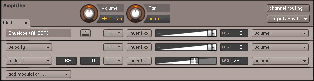
The Modulation Router of an Amplifier Module
If a Modulation Router entry uses an internal modulation source for the assignment, you’ll always find a corresponding modulation source panel at the bottom of the Rack in Instrument Edit mode; here you can adjust the parameters of the signal source, such as an LFO’s frequency or envelope timings.
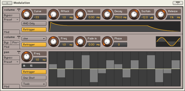
The Modulation section contains all internal modulation sources used in your Instrument.
You don’t need to scroll up and down to make adjustments to a modulation source and its Modulation Router entry, though; clicking one of the Quick-Jump buttons on both panels or simply pressing the “^” key (“~” on US keyboards) will instantly bring you to the respective other panel.

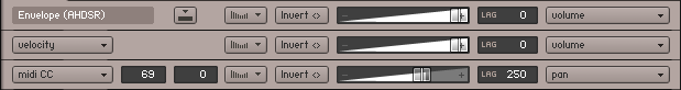
The Quick-Jump button on Modulation Router entries and modulation source panels brings you to the respective other panel.
Adding a new entry to a Modulation Router table, thereby creating a new modulation assignment, can be done in one of two different ways. Which one you choose largely depends on your personal preference.
Right-click the knob of a parameter that you want to modulate, then choose a modulation source from the drop-down menu which appears. The submenu at the bottom of this menu contains modulation sources which already exist in your Instrument (if any), and allows you to assign an existing source to more than one parameter. If the module’s Modulation Router is not currently visible, adding a new assignment will show it. This allows you to make immediate adjustments to the assignment parameters.
Open the Modulation Router of a module and click the Add Modulator button on the left side of its last row. This will open the same drop-down menu of modulation sources that you’ll get when you right-click a knob. Since you can’t specify a destination parameter this way, you’ll usually have to change the modulated parameter via the drop-down menu on the right side of the new assignment entry.
Deleting Modulation Assignments
To get rid of a modulation assignment entirely, select its entry in the Modulation Router by clicking on its panel, then press the Delete key on your keyboard. If the assignment was using an internal signal source, and no other assignments in your Instrument are using the same source, the corresponding source panel will disappear from the Modulation section of the Rack as well.
You can also right-click on the modulation assignment and select Delete from the context menu.
Assignment Controls
As mentioned, all controls which affect the behavior of a modulation source can be found on the respective source panel at the bottom of the Rack. There are additional parameters, though, that affect in which way this source module’s output signal will be mapped to the parameter to which it has been assigned. Since a source can be used to modulate multiple parameters in different ways, it wouldn’t make much sense to include these controls on the panel of the source; instead, they’re a part of each assignment entry in the Modulation Router table.
From top to bottom, this Modulation Router contains entries for a volume envelope, a velocity-to-volume mapping, and a mapping which uses MIDI CC #69 data for the panorama position, with using the far left as default.
Modulation Source: If the entry belongs to an internal source assignment, this value can’t be modified, but external source assignments will offer a drop-down menu here that allows you to switch to a different source.
Quick-Jump button (only visible on internal source assignments, like LFOs): Clicking on this button will immediately scroll down to the respective source’s control panel at the bottom of the Rack. Once you’re finished with your adjustments down there, the identical button on the panel will bring you back to where you came from.
MIDI CC Number (only visible if source is MIDI CC): The modulation will acquire its values from incoming MIDI controller data with the number specified here. The modulation wheel usually sends MIDI CC #1 data, volume and expression pedals CC #7 and #11, respectively.
MIDI CC Default Value (only visible if source is MIDI CC): As a MIDI controller’s current position can’t be queried remotely and is thus unknown until actual data is received, this value will be used as a substitute until the first MIDI CC data is seen. A value of -1 in this field tells Kontakt not to modulate the parameter at all until actual data is received.
Modulation Shaper: If you need more control over the relationship between modulation signals and parameter changes than what’s provided by the Intensity fader, clicking on this button will open a shaper table, which allows you to create all sorts of custom shapes — from non-linear transfer curves all the way to complex tables that assign each possible input value to a different output value.
The Modulation Shaper
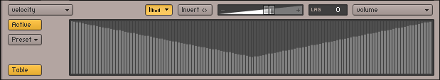
A modulation shape which changes low velocity values to higher ones.
The Active button in the upper left corner of this view activates the shaping of the modulation signal. When switched on, the window next to it will show a graphical representation of the table that’s made up of 128 vertical bars, with each bar’s height representing the actual value that will be used for modulation if the value that corresponds to this bar is received from the source module. In other words, what you see is a transfer curve, whose X axis represents the input value, and whose Y axis represents the output value.
By clicking and dragging a single bar, drawing shapes across bars, or drawing lines by right-clicking and dragging the mouse, you can quickly create your own shapes. Note that holding the [Shift] key while changing the height of a bar allows for finer editing, while [Ctrl]-clicking on bars ([Cmd]-click on Mac OS X) will reset them to zero.
Table: When active, the Modulation Shaper provides an alternate editing mode for non-linear curves and other deterministic shapes that are not easily drawn with any accuracy using a mouse.
Tip
When using this Table mode of editing the modulation shape, you have the option to import and export the table data as a text file. To open the export dialog, [Shift]-click the Active button; and to open the import dialog, use [Shift] + [Ctrl] on Windows or [Shift] + [Cmd] on Mac OS X.
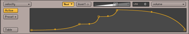
The curve editor allows you to create continuous, smooth modulation shapes.
Table: When deactivated, you can define your mapping using curve segments. This editor mode works similarly to the flexible envelope editor described in section Flexible Envelopes. You can drag the endpoints of curve segments to move them, drag the circles in the middle of a segment to change the curve shape, right-click [Ctrl](macOS) + click on an endpoint to delete it, and right-click [Ctrl](macOS) + click somewhere else to create a new segment.
Invert button: If this button is activated, all modulation will be reversed in direction; so a rise in the modulation signal will result in a proportional drop in parameter value.
Modulation Intensity: This fader controls how large the parameter changes caused by the modulation signal changes will be, or in other words, how far this assignment will cause the parameter to stray from its original value. As different modulation intensities can produce considerably different effects, this is probably the most important parameter of the assignment. As an example, reconsider the LFO-to-pitch assignment described in the previous section: a natural and subtle instrument vibrato will call for a rather low intensity value, while a higher intensity will produce a sound reminiscent of a police siren.
Lag (Smoothing): If this value is higher than 0, any signal received from the modulation source will be smoothed. The displayed value is a time constant in milliseconds and indicates how long the smoothed signal would take to reach the new value after an instantaneous change in the modulation signal occurred. The most obvious application of this feature is a gentle smoothing of external MIDI data; as the MIDI standard imposes a resolution of only 128 steps on controller data, using it without smoothing is prone to causing audible parameter jumps. A fairly low smoothing value will get rid of these, while still preserving a sufficiently fast response to controller changes. As pitch modulation is particularly prone to audible steps, all pitch assignments will have their Smoothing parameter set to a value of 250 by default. Higher values can give useful results with LFOs, such as a “slurred” rectangle or sawtooth modulation.
Modulation Target: Finally, the rightmost element displays the parameter that will be modulated. If you click the field, a drop-down list of all parameters that can be modulated in this module will appear, and you can choose a new target.